
Exhaust butterfly valve for auxiliary braking of automobile

An exhaust butterfly valve and automobile auxiliary technology, applied in the direction of engine control, machine/engine, mechanical equipment, etc., can solve problems such as difficult to increase reset force, unsmooth reset, reset failure, etc., to achieve high promotion and application value, reduce Effect of small operating torque and reduced energy loss

Active Publication Date: 2014-03-05
DFSK MOTOR LTD CHONGQING BRANCH CO
View PDF7 Cites 6 Cited by
  • Summary
  • Abstract
  • Description
  • Claims
  • Application Information

AI Technical Summary

Problems solved by technology

Generally, the valve plate will be reset under the action of the return spring of the power mechanism, but due to its own nature and the use environment, the return spring will appear stuck after a long time of use, resulting in unsmooth reset or even reset failure; and subject to The elastic force limit of the return spring, it is difficult to increase the return force by unilaterally increasing the spring force

Method used


Image

  • Exhaust butterfly valve for auxiliary braking of automobile
  • Exhaust butterfly valve for auxiliary braking of automobile
  • Exhaust butterfly valve for auxiliary braking of automobile

Examples


Embodiment Construction

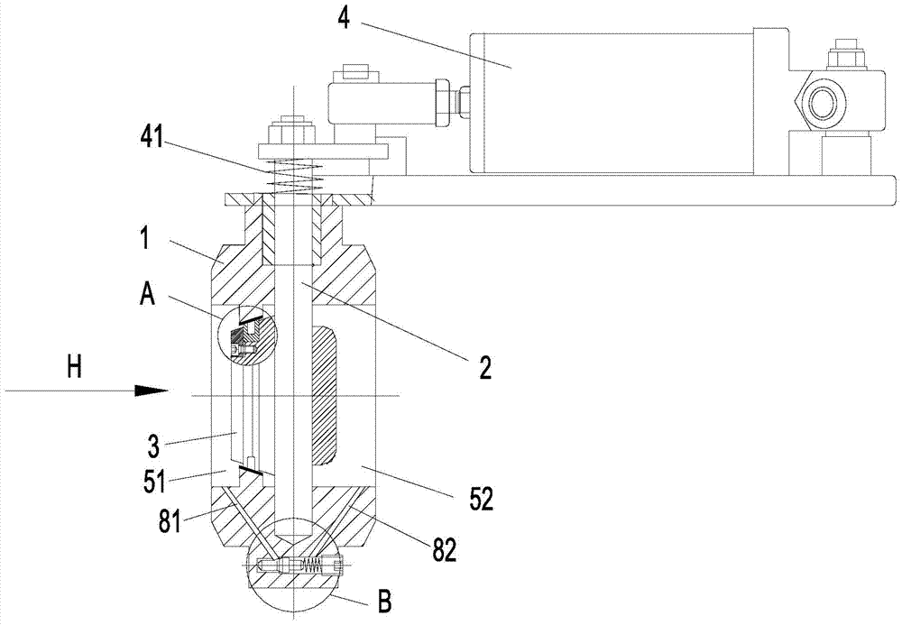
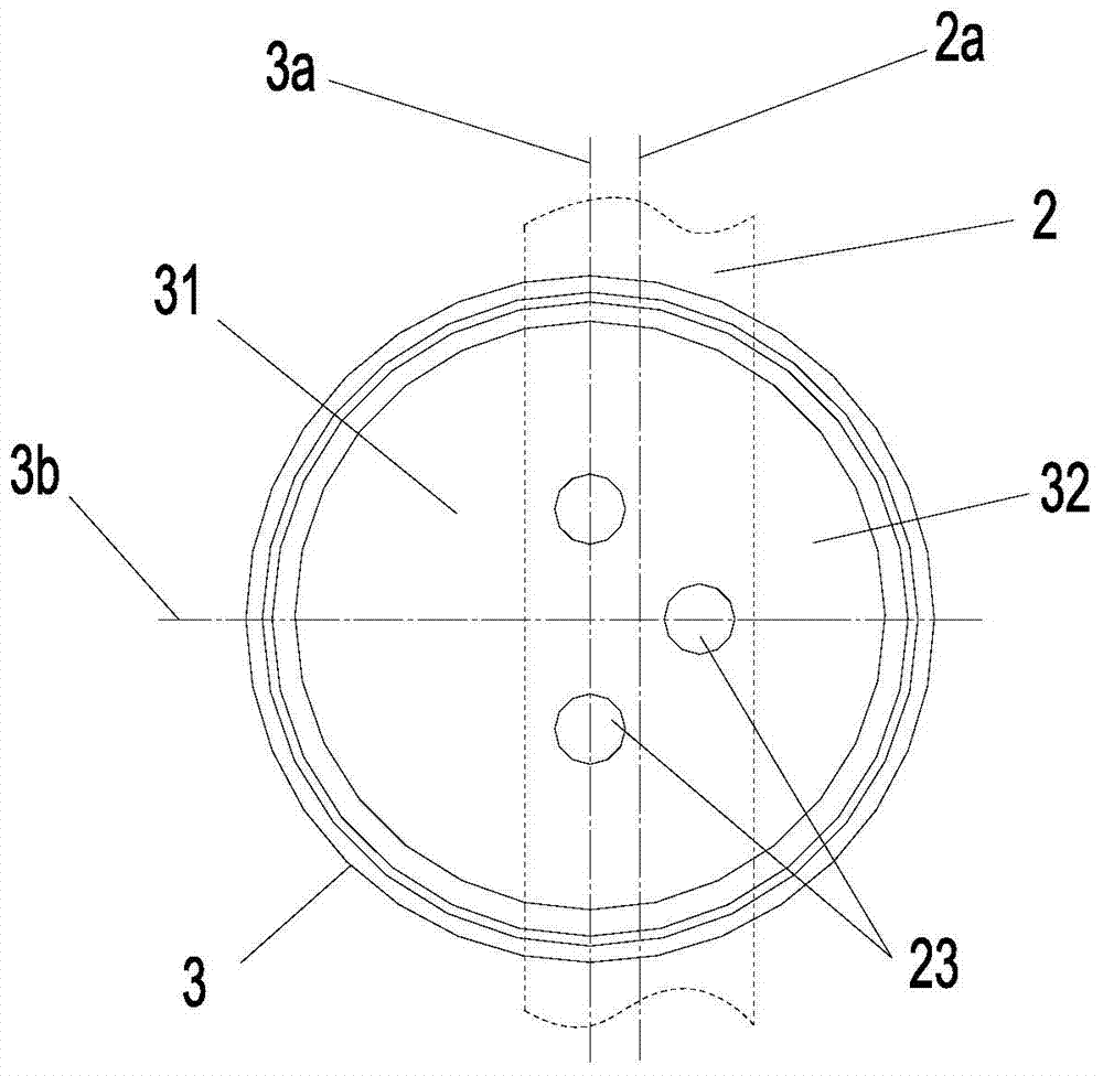
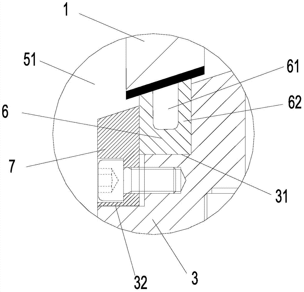
[0022] figure 1 It is a structural schematic diagram of the present invention, figure 2 for figure 1 H direction view in, image 3 for figure 1 The magnified view at A in the middle, Figure 4 for figure 1 The enlarged view at the B place in the middle is as shown in the figure: the exhaust butterfly valve for automobile auxiliary braking in this embodiment includes a valve body 1, a valve stem 2, a valve plate 3 and a power mechanism 4, and when the valve plate 3 is closed, it will The inner cavity is divided into an air intake chamber 51 and an exhaust chamber 52, the valve plate 3 is connected with the power mechanism 4, and the power mechanism 4 drives the valve plate 3 to rotate on the valve stem 2 as a rotating shaft. When the valve plate 3 is closed, the inner cavity is divided into an air intake chamber 51 and an exhaust chamber 52. The valve plate 3 is left-right and up-down symmetrical, and the axis 2a of the valve stem 2 deviates from the The left and right s...


PUM


Abstract

The invention discloses an exhaust butterfly valve for auxiliary braking of an automobile. The exhaust butterfly valve for auxiliary braking of the automobile comprises a valve body, a valve rod, a valve plate and a power mechanism, wherein the valve plate is fixedly arranged in an inner cavity of the valve body through the valve rod, the valve plate is connected with the power mechanism, the power mechanism drives the valve plate to overturn in the inner cavity by using the valve rod as a rotary axis, when the valve plate is closed, the inner cavity is divided into a gas inlet cavity and an exhaust cavity by the valve plate, the valve plate is in bilateral symmetry and longitudinal symmetry, the axis of the valve rod deviates from the bilateral symmetry axis of the valve plate so that one surface, facing the gas inlet cavity, of the valve plate can be divided into a pressure surface I and a pressure surface II by the longitudinal plane of the axis, and the pressure surface I and the pressure surface II are different in size. According to the exhaust butterfly valve for auxiliary braking of the automobile, due to the fact that the valve plate and the valve rod are eccentrically installed, the surface, facing the gas inlet cavity, of the valve plate is divided into the pressure surface I and the pressure surface II, the pressure surface I and the pressure surface II are different in size, reset force of the exhaust butterfly valve in the process of removing exhaust braking is increased through the pressure difference between the two pressure surfaces, operating torque can be reduced when the valve plate is open, the energy loss of an engine is reduced, flexibility of opening of the valve plate is ensured, and normal operation of the exhaust braking function of the engine is ensured.

Description

technical field [0001] The invention relates to a component for auxiliary braking of automobiles, in particular to an exhaust butterfly valve for auxiliary braking of automobiles. Background technique [0002] With the increasing requirements of commercial vehicles on the braking system, only relying on upgrading the traditional braking system can no longer fully meet the needs of customers, so auxiliary braking has emerged as the times require, although the auxiliary braking cannot reach the main braking system Such a large braking force is output, but when the vehicle needs to decelerate during driving, the use of auxiliary braking not only reduces the wear of the friction lining, but also has the effect of braking and decelerating. Exhaust brake is a kind of deceleration brake that assists the braking effect of the vehicle. It has a simple structure and low price, and is widely used in trucks or buses equipped with diesel engines. The exhaust brake system usually install...

Claims


Application Information

Patent Timeline
Patent Type & Authority Applications(China)
IPC IPC(8): F02D9/10F02D9/06
Inventor 张兴海
Owner DFSK MOTOR LTD CHONGQING BRANCH CO
Learn More