Cylinder structure of hydraulic vertical conveying device

A technology for conveying devices and oil cylinders, applied in the direction of fluid pressure actuating devices, etc., which can solve the problems of potential safety hazards, damage, and increased difficulty of operation for operators, and achieve the effect of ensuring long-lasting use

Active Publication Date: 2015-12-23
CHANGSHU TONGRUN AUTO REPAIRING EQUIP
View PDF8 Cites 0 Cited by
  • Summary
  • Abstract
  • Description
  • Claims
  • Application Information

AI Technical Summary

Problems solved by technology

[0004] However, the technical solution disclosed in the above-mentioned CN102225713B still has the following shortcomings in actual use: First, the pressure oil in the cylinder cavity (also called the piston rod cavity) of the oil cylinder enters the oil cylinder when the operator operates the oil return valve. In the process of the oil storage chamber between the body and the outer casing, due to the high pressure of the piston rod carrying the heavy object, although the piston rod has the advantage of fast downward speed to improve the working efficiency, the pressure oil in the oil cylinder is always The oil return passage between the cylinder chamber and the oil storage chamber (when the oil return valve is opened) rushes down to the oil storage chamber, so the intake and exhaust ports that are arranged on the outer casing by thread fit and communicate with the oil storage chamber Screws (the industry is accustomed to refer to the intake and exhaust screws as breathing screws) often have oil injection, which on the one hand causes pollution, and on the other hand affects the function of the hydraulic conveying device due to the loss of hydraulic oil; The piston rod returns too quickly, that is, it moves toward the cylinder cavity quickly, so there are safety hazards, such as the risk of damage to the oil cylinder and the risk of falling heavy objects; third, because the piston rod returns instantly, it cannot be guaranteed. motion smoothing effect
[0005] Theoretically speaking, when the piston rod goes up, the amount of air that enters the oil storage chamber from the thread gap between the intake and exhaust screw and the outer sleeve is the same as the air that is discharged from the oil storage chamber by the intake and exhaust screw when the piston rod goes down. The quantity is basically balanced, however, this is only a design concept based on the fact that the upward speed of the piston rod is basically equal to the downward speed, because when the piston rod with a heavy load suddenly descends, the air in the oil storage chamber is bound to move forward. The exhaust screw is dumped, resulting in unavoidable fuel injection
In order to prevent the oil injection of the intake and exhaust screws as much as possible, the current solution is to manually control the opening degree of the oil return valve by the operator. The difficulty of operation has increased significantly, especially in the actual operation process, it is often difficult to properly grasp

Method used


Image

  • Cylinder structure of hydraulic vertical conveying device
  • Cylinder structure of hydraulic vertical conveying device
  • Cylinder structure of hydraulic vertical conveying device

Examples


Embodiment

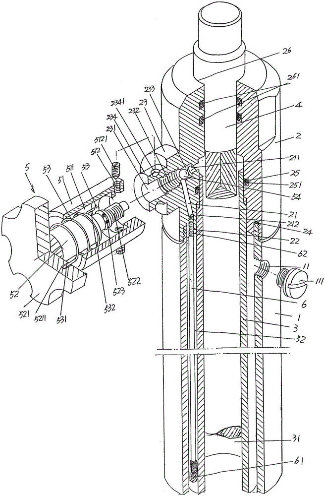
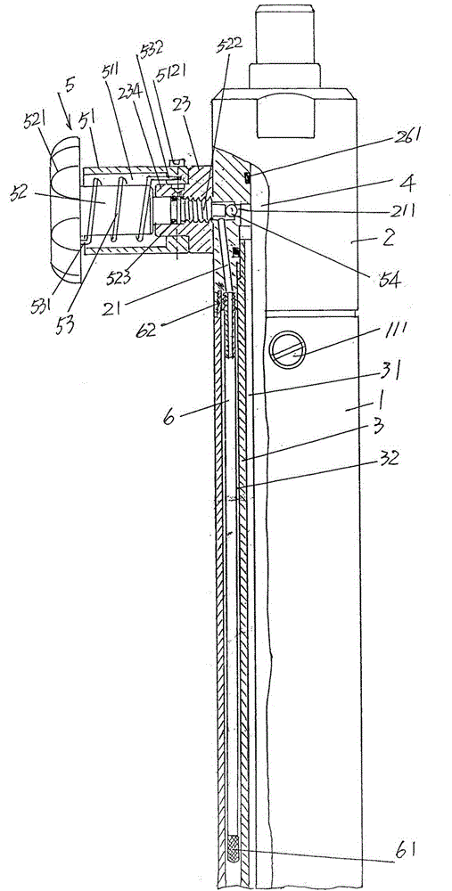
[0024] See figure 1 and figure 2 , provides an outer cover 1, the outer cover 1 is made of metal material, on the outer cover 1 and at the upper part of the outer cover 1, namely the upper end, there is an intake and exhaust screw thread matching hole 11, and in the intake and exhaust screw thread matching hole 11 The position is screwed with an intake and exhaust screw 111 in a threaded fit. A cap 2 is provided, and the top cap 2 is preferably fixed to the upper end of the outer casing 1 in a threaded fitting manner, and a top cap sealing ring 24 is provided at the matching position between the top cap 2 and the outer casing 1 . As shown in the figure, an oil return passage 21 is provided on the top cap 2, because a valve seat 23 that is significantly protruding from the outer wall surface of the top cap 2 is formed on the outer wall of the top cap 2, and the valve seat 23 is located on the top cap. The position on the top cap 2 corresponds to the oil return passage 21, so...


PUM


Abstract

The invention provides an oil cylinder structure of a hydraulic upright conveyer, and belongs to the technical field of conveying equipment. The cylinder structure of the hydraulic upright conveyer comprises a jacket, a top cap, an oil cylinder, a piston rod and an oil return valve, wherein a gas feeding and discharging screw is arranged in the jacket in a screwed manner; the top cap is fixed with the upper end of the jacket; an oil return passage is formed in the top cap; the oil cylinder is arranged in the jacket; an oil cylinder cavity is communicated with the oil return passage; an oil storage cavity is formed between the outer wall of the oil cylinder and the inner wall of the jacket; the piston rod is arranged in the oil cylinder cavity and is matched with the top cap at the upper end of the piston rod; the oil return valve is arranged on the top cap and corresponds to the oil return passage; and a threaded matching hole of the gas feeding and discharging screw in the jacket is communicated with the oil storage cavity. The oil cylinder structure of the hydraulic upright conveyer is characterized by also comprising an oil return pipe which is arranged in the oil storage cavity; and the upper end of the oil return pipe is connected with the top cap at a position corresponding to the oil return passage. The speed of hydraulic oil flowing to the storage cavity from the oil cylinder cavity can be obviously reduced, the loading piston rod can slowly move towards the oil cylinder cavity, and the hydraulic oil in the oil storage cavity can be prevented from spraying outwards from a matching gap between the gas feeding and discharging screw and the threaded matching hole of the gas feeding and discharging screw.

Description

technical field [0001] The invention belongs to the technical field of conveying equipment, and in particular relates to an oil cylinder structure of a hydraulic vertical conveying device. Background technique [0002] In vehicles, especially in the auto repair industry and mechanical equipment maintenance departments such as power equipment maintenance departments of enterprises, the situation of using transport devices is usually encountered. Take the auto repair industry such as the auto repair factory as an example. After the vehicle is lifted by the lifting device or the lifting device is lifted, when disassembling parts such as gearboxes and exhaust pipes, in order not to fall damage and avoid causing harm to maintenance personnel Therefore, it is necessary to support parts such as the disassembled gearbox, exhaust pipe and oil pan by means of a transport device, and move them to the repair site for repair after disassembly. [0003] The technical information of the a...

Claims


Application Information

Patent Timeline
Patent Type & Authority Patents(China)
IPC IPC(8): F15B15/14
Inventor 王胜唐循申严袁陈晓杰
Owner CHANGSHU TONGRUN AUTO REPAIRING EQUIP
Why Eureka
Try Eureka