
An optical test platform

A test platform and optical technology, applied in optical instrument testing, machine/structural component testing, measuring devices, etc., can solve the problems of large repetitive workload, high cost, cumbersome and other problems, and achieve the effect of ensuring reliability and saving costs.

Active Publication Date: 2016-02-24
BEIJING INFORMATION SCI & TECH UNIV
View PDF5 Cites 0 Cited by
  • Summary
  • Abstract
  • Description
  • Claims
  • Application Information

AI Technical Summary

Problems solved by technology

Since it is necessary to adjust different angles of the loaded experimental platform and replace different test products during the test, when changing a test product or adjusting an angle, it is necessary to move the carrier back for replacement and adjustment, and then re-test, thus repeating the workload big and very cumbersome
Especially for the flight carrier loaded with optical products, the cost of air-ground reciprocation is relatively expensive
[0003] At present, there is no experimental platform capable of testing different positions and postures of visible light and infrared optical products at the same time, helping to understand and evaluate the reliability and stability of optical products.

Method used


Image

  • An optical test platform
  • An optical test platform
  • An optical test platform

Examples


Embodiment Construction

[0018] The present invention will be described in detail below in conjunction with the accompanying drawings and embodiments.

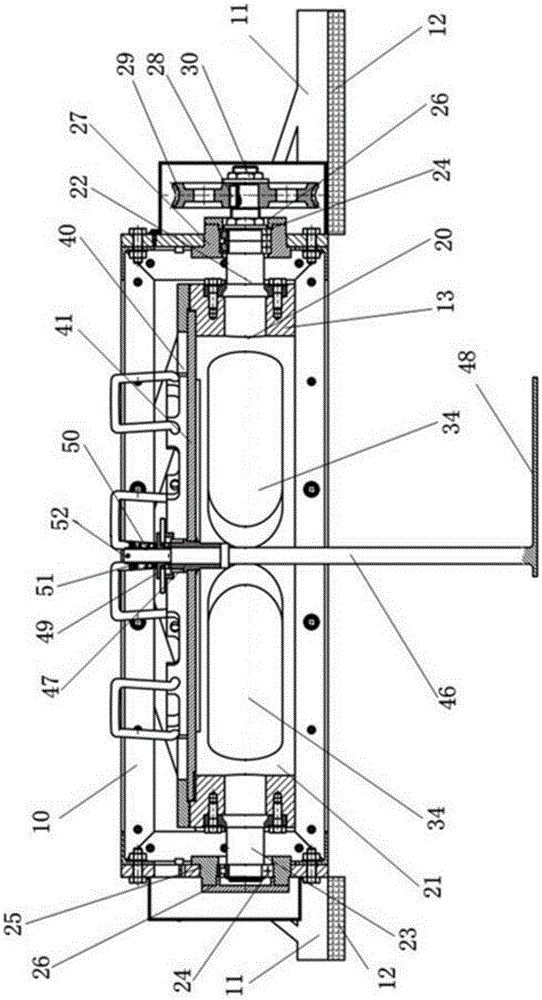
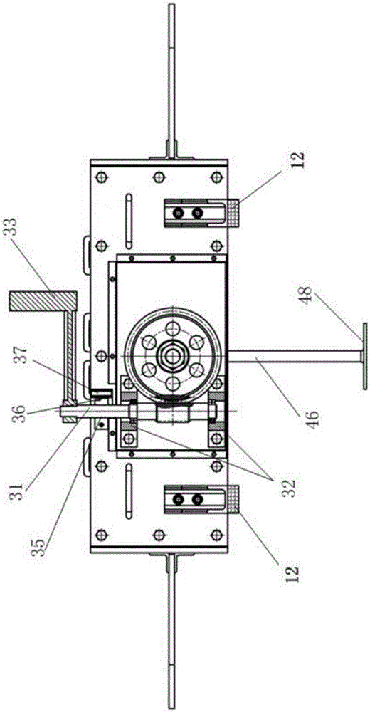
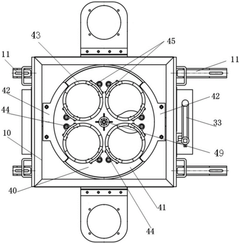
[0019] Such as Figure 1 ~ Figure 3 As shown, the present invention provides an optical test platform, which includes a test platform support 10 , a swing adjustment mechanism 20 and a rotation adjustment mechanism 40 . A swing adjustment mechanism is installed inside the test platform bracket 10, and the rotation adjustment mechanism 40 is installed on the upper part of the swing adjustment mechanism 20, and the rotation adjustment mechanism 40 and the swing adjustment mechanism are flexibly connected.

[0020] Such as figure 1 , image 3 As shown, two connection frames 11 are fixedly connected respectively on the left side wall and the right side wall of the test platform support 10, and a position adjustment block 12 is arranged below each connection frame 11. By replacing the position adjustment blocks 12 of different heights, the Realize the h...


PUM


Abstract

The invention relates to an optical test platform. The optical test platform comprises a test platform support, wherein a swing adjustment mechanism is arranged inside the test platform support, and a rotation adjustment mechanism is arranged on the upper portion of the swing adjustment mechanism. The swing adjustment mechanism comprises a swing working table, wherein the two sides of the swing working table are fixedly connected with a turbine shaft and a rear shaft respectively, the rear shaft is connected with a first rolling bearing and connected with the left side wall of the test platform support through a rear shaft base and the first rolling bearing, and the outer side of the rear shaft base is sealed and protected through a bearing end cover. The turbine shaft is connected with the right side wall of the test platform support through a turbine shaft base, the turbine shaft is connected with a second rolling bearing and a third rolling bearing and connected with the right side wall of the test platform support through the turbine shaft base and the two rolling bearings, and the outer side of the turbine shaft base is sealed and protected through the other bearing end cover. The end, extending out of the test platform support, of the turbine shaft is connected with a turbine through keys, the turbine is connected with a worm, and the worm is fixed to the test platform support through two worm bearing bases.

Description

technical field [0001] The invention relates to a test platform for loading test components, in particular to an optical test platform for loading optical test products for detecting three-dimensional scenes by using a mobile carrier. Background technique [0002] At present, when performing experiments on visible light and infrared optical products, it is often necessary to carry out image acquisition and position and attitude data collection of optical products in different positions and attitudes to analyze the optical test of the product and its overall performance. Since it is necessary to adjust different angles of the loaded experimental platform and replace different test products during the test, when changing a test product or adjusting an angle, it is necessary to move the carrier back for replacement and adjustment, and then re-test, thus repeating the workload Big and very cumbersome. Especially for the flight carrier loaded with optical products, the air-groun...

Claims


Application Information

Patent Timeline
Patent Type & Authority Patents(China)
IPC IPC(8): G01M11/00
Inventor 马超赵自强刘令涛王少红
Owner BEIJING INFORMATION SCI & TECH UNIV
Learn More