Method for testing reactive compensation device without dismounting leads

A compensating device and lead wire technology, applied in the direction of measuring devices, measuring electricity, measuring electrical variables, etc., can solve the problems of time-consuming, laborious, long-term, easy to appear safety hazards, etc., to reduce maintenance costs, find and eliminate safety hazards. , the effect of ensuring the reliability of power supply

Inactive Publication Date: 2014-03-05
PINGDINGSHAN POWER SUPPLY ELECTRIC POWER OF HENAN
View PDF3 Cites 7 Cited by
  • Summary
  • Abstract
  • Description
  • Claims
  • Application Information

AI Technical Summary

Problems solved by technology

Due to the large number of components in the device, according to conventional requirements, all components must be disassembled for inspection and testing, analysis of test data, and finding faulty components. This often takes a long time, and reassembly after disassembly is time-consuming and laborious. prone to safety hazards

Method used


Image

  • Method for testing reactive compensation device without dismounting leads
  • Method for testing reactive compensation device without dismounting leads
  • Method for testing reactive compensation device without dismounting leads

Examples


Embodiment 1

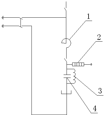
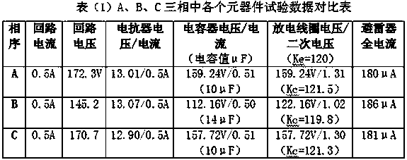
[0030] Using the method of testing the reactive power compensation device without removing the lead wires of the present invention to detect the reactive power compensation device in a 35KV substation includes the following steps:

[0031] 1) Test phase A: introduce the AC operating voltage into the reactive power compensation device, and use a peak clamp ammeter to measure the full current of the arrester to be 180μA;

[0032] 2) Disconnect the AC operating voltage of the reactive power compensation device, add AC test voltage to both ends of the reactive power compensation device, so that the current of the circuit reaches 0.5A, and the detection circuit voltage is 172.3V;

[0033] 3) Use a voltmeter and an ammeter to test the voltage and current at both ends of the reactor for three times, and the results of the three tests are 13.01V, 0.5A; 13.04V, 0.5A; 12.96V, 0.5A;

[0034] 4) Use a voltmeter and an ammeter to test the voltage and current at both ends of the capacitor f...

Embodiment 2

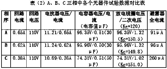
[0043] Using the method of testing the reactive power compensation device without removing the lead wires of the present invention to detect the reactive power compensation device in a certain 110KV substation includes the following steps:

[0044] 1) Test phase A: introduce the AC operating voltage into the reactive power compensation device, and use a peak clamp ammeter to measure the full current of the arrester to be 91μA;

[0045] 2) Disconnect the AC operating voltage of the reactive power compensation device, add 110V AC test voltage to both ends of the reactive power compensation device, and the detection circuit current is 0.65A;

[0046] 3) The voltage and current at both ends of the reactor were tested three times with a voltmeter and an ammeter, and the results of the three tests were 11.21V, 0.65A; 11.23V, 0.64A; 11.19V, 0.66A;

[0047] 4) Use a voltmeter and an ammeter to test the voltage and current at both ends of the capacitor for three times, and the results ...


PUM


Abstract

The invention discloses a method for testing a reactive compensation device without dismounting leads. According to the method, under the condition that the leads of various components of the reactive compensation device are not dismounted, the full current of a lightning arrester is measured so as to detect the internal performance of the lightning arrester; the full current or full voltage of the reactive compensation device and the voltage values and current values of the various components like an electric reactor, a capacitor and a discharge coil are tested respectively by switching off the alternating-current operating voltage of the reactive compensation device and adding an alternating-current testing voltage to the two ends of the reactive compensation device. In this way, on the one hand, the quality of the various components can be judged by comparing measured parameters with rated performance parameters of the various components, and a fault phase can be determined according to the deviation of measured results of the full current or full voltage; on the other hand, the component of which measured values have a large deviation can be found by comparing the various components, in the A phase, the B phase and the C phase, of the reactive compensation device through the 'three-comparison' method, and accordingly the fault phase and the fault component of the reactive compensation device can be determined.

Description

technical field [0001] The invention relates to the technical field of reactive power compensation device maintenance, in particular to a method for testing a reactive power compensation device without removing lead wires. Background technique [0002] The reactive power compensation device occupies an important position in electrical equipment because of its functions of reducing loss and saving energy, stabilizing system voltage, and improving power quality. It is widely used in power systems. It consists of reactors, capacitors, discharge coils, lightning arresters, Composed of switches and connecting wires. Affected by various factors during the operation of the power grid, reactive power compensation devices often trip. Due to the large number of components in the device, according to conventional requirements, all components must be disassembled for inspection and testing, analysis of test data, and finding faulty components. This often takes a long time, and reassemb...

Claims


Application Information

Patent Timeline
Patent Type & Authority Applications(China)
IPC IPC(8): G01R31/00
Inventor 裴继东蒋延磊张军彭磊亚赵志南银高胜韩向林
Owner PINGDINGSHAN POWER SUPPLY ELECTRIC POWER OF HENAN
Why Eureka
Try Eureka