Liquid crystal lens and stereo display device with same

A technology of liquid crystal lens and liquid crystal lens array, which is applied in the direction of static indicators, optics, instruments, etc., and can solve the problems of complex design of the drive circuit and the peripheral circuit of the liquid crystal lens array

Active Publication Date: 2014-03-05
中航华东光电有限公司
View PDF5 Cites 12 Cited by
  • Summary
  • Abstract
  • Description
  • Claims
  • Application Information

AI Technical Summary

Problems solved by technology

[0005] In 3D display, a symmetrical voltage needs to be applied to each strip electrode, such as V(S11)=V(S19)>V(S12)=V(S18)>V(S13)=V(S17)>V( S14)=V(S16)>V(S15), as the number of electrodes in the design of each liquid crystal lens unit increases, the number of different driving voltages that need to be provided also increases, resulting in changes in the design of the driving circuit and the peripheral circuit of the liquid crystal lens array. complicated

Method used


Image

  • Liquid crystal lens and stereo display device with same
  • Liquid crystal lens and stereo display device with same
  • Liquid crystal lens and stereo display device with same

Examples


Embodiment 1

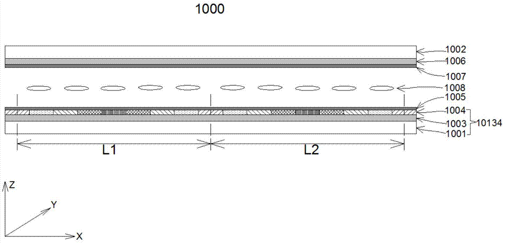
[0039] like image 3 As shown, the liquid crystal lens array 1000 of this embodiment includes a plurality of liquid crystal lens units (only two lens units L1 and L2 are shown in the figure), and each lens unit such as L1 and L2 has the same structure. The liquid crystal lens array 1000 includes a first substrate 1001 and a second substrate 1002. The first substrate 1001 and the second substrate 1002 are arranged facing each other, and are generally made of transparent materials such as glass. A first electrode 1003 is provided on the first substrate 1001. The first electrode 1003 is a surface electrode without a special pattern, and is generally made of a transparent conductive material such as ITO or IZO. A first dielectric layer 1004 is disposed on the first electrode 1003, and a first alignment film 1005 is disposed on the first dielectric layer 1004. The first alignment film 1005 is generally made of organic materials such as polyimide. The second electrode 1006 is dispo...

Embodiment 2

[0057] like Figure 11 As shown, in this embodiment, a transparent insulating layer 2011 is set on the first dielectric layer 2004. Other implementation modes are the same as in Embodiment 1. The preferred transparent insulating layer 2011 should have a high dielectric coefficient to reduce the (It can be seen from the formula (5) that for capacitors in series, the larger the capacitor, the smaller the voltage), so that the driving voltage will not be increased. Since each region in the liquid crystal lens unit needs to accurately control the voltage V applied to both sides of the liquid crystal layer 2008 LC , according to V=V LC +V e , that is, it is necessary to accurately control the V on the dielectric layer 2004 e size, due to V e =Q / C e =QHe / ε 0 εS, when V e When the size is determined, it can be adjusted by adjusting the dielectric coefficient ε of each strip-shaped dielectric block and the thickness He of the strip-shaped dielectric block of the dielectric laye...


PUM


Abstract

The invention discloses a liquid crystal lens and a stereo display device with the liquid crystal lens. A first dielectric layer comprises an odd number of strip-shaped dielectric blocks which are sequentially arranged in the X direction and extend in the Y direction in parallel. The widths of the strip-shaped dielectric blocks are the same and are sequentially marked as d11, d12, d13,..., d18, d1n, electric conduction coefficients of the strip-shaped dielectric blocks are distributed symmetrical to the strip-shaped dielectric block in the width of d1((n+1)/2), the electric conduction coefficient of the strip-shaped dielectric block in the width of d1((n+1)/2) is the smallest, and the electric conduction coefficient of the strip-shaped dielectric block in the width of d11 and the electric conduction coefficient of the strip-shaped dielectric block in the width of d1n are the largest and the same, in other words, the electric conduction coefficients of lens units gradually decrease from the edge of the lens to the center of the lens. An electric field which is distributed in a left and right symmetrical mode is formed in each lens unit and gradually changes from the edge of the lens to the center of the lens, and therefore the overall refractive index of the liquid crystal layer gradually changes, the effect similar to that of convex lens focusing is achieved, and the liquid crystal lens can be widely applied to naked eye 3D stereo display and can be freely switched between 2D and 3D.

Description

technical field [0001] The invention relates to a liquid crystal lens, in particular to a liquid crystal lens and a stereoscopic display device using the same. Background technique [0002] The three-dimensional display device that uses liquid crystal lenses to realize free three-dimensional display mainly uses the positive and negative electrodes respectively arranged on the two substrates on both sides of the liquid crystal layer, and applies driving voltages of different sizes to different electrodes, so as to create a positive and negative electrode between the two substrates. Vertical electric fields with different strengths are formed to drive liquid crystal molecules to align to form a variable-focus liquid crystal lens. Therefore, it is only necessary to control the voltage distribution on the corresponding electrodes, and the refractive index distribution of the liquid crystal lens will be changed accordingly, so as to control the distribution of light emitted by th...

Claims


Application Information

Patent Timeline
Patent Type & Authority Applications(China)
IPC IPC(8): G02F1/29G02F1/1343G02F1/1337G02F1/133G02B27/22
Inventor 向贤明李建军董戴许召辉
Owner 中航华东光电有限公司
Why Eureka
Try Eureka