Controlling method of bridge type inverter and controlling device

A technology for converting circuits and control methods, applied to output power conversion devices, control/regulation systems, DC power input conversion to DC power output, etc., which can solve problems such as increasing system costs and reducing overall system efficiency

Active Publication Date: 2014-03-05
EAST GRP CO LTD
View PDF4 Cites 17 Cited by
  • Summary
  • Abstract
  • Description
  • Claims
  • Application Information

AI Technical Summary

Problems solved by technology

But the disadvantage of this is that it increases the system cost and reduces the overall efficiency of the system

Method used


Image

  • Controlling method of bridge type inverter and controlling device
  • Controlling method of bridge type inverter and controlling device
  • Controlling method of bridge type inverter and controlling device

Examples


Embodiment 1

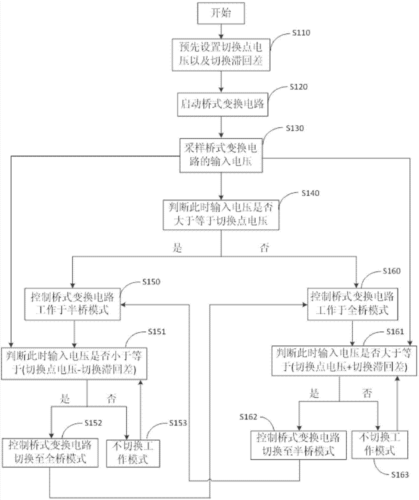
[0062] Please refer to figure 1 , figure 1 It is a flow chart of the control method of the bridge conversion circuit 20 of the first embodiment. The control method of the bridge conversion circuit 20 proposed in this embodiment includes:

[0063] S110 , preset the switching point voltage Vs and the switching hysteresis difference ΔV of the bridge conversion circuit 20 .

[0064] Determine the input voltage range of the bridge conversion circuit 20 according to the output voltage of the photovoltaic power source 50, such as V1 is the lowest input voltage of the bridge conversion circuit 20, V2 is the highest input voltage of the bridge conversion circuit 20, Vs is the switching point voltage, Vs Between V1 and V2, the switching hysteresis difference ΔV is smaller than V2-V1.

[0065] S120, start the bridge conversion circuit 20.

[0066] S130 , sampling the input voltage Vp of the bridge conversion circuit 20 .

[0067] After the bridge conversion circuit 20 is started, th...

Embodiment 2

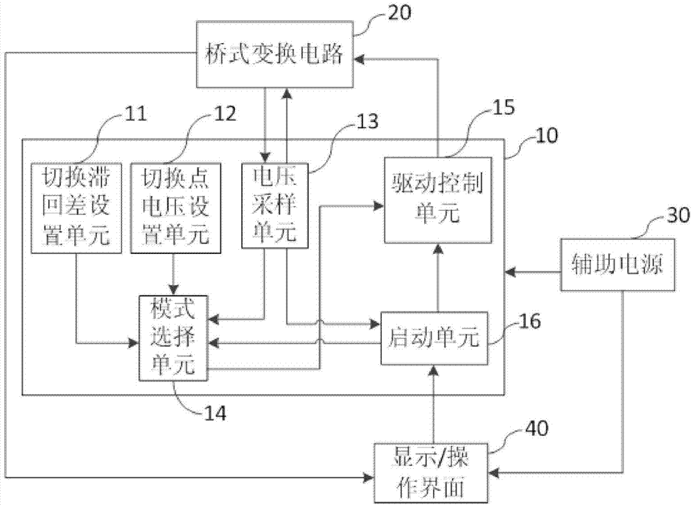
[0104] Please refer to image 3 , image 3 It is a structural principle diagram of the control device of the bridge conversion circuit of the second embodiment. The control device 10 of the bridge conversion circuit 20 proposed in this embodiment includes a voltage sampling unit 13 , a mode selection unit 14 , a drive control unit 15 , a switching hysteresis difference setting unit 11 , a switching point voltage setting unit 12 and a starting unit 16 .

[0105] Wherein, the voltage sampling unit 13 is used for sampling the input voltage Vp of the bridge conversion circuit 20; the mode selection unit 14 is used for according to the current working mode of the bridge conversion circuit 20, the input voltage Vp, the preset switching point voltage Vs and the preset The switching hysteresis difference ΔV generates a corresponding mode selection signal; the drive control unit 15 is used to output a corresponding drive control signal to the control terminal of the bridge conversion ...


PUM


Abstract

The invention discloses a controlling method of a bridge type inverter and a controlling device. The controlling method comprises the following steps of sampling an input voltage Vp of the bridge type inverter, generating a corresponding mode selection signal according to a current operation mode of the bridge type inverter, the input voltage Vp, a presupposed switching point voltage Vs as well as a presupposed switching hysteresis difference deltaV, and outputting a corresponding driving control signal to a control end of the bridge type inverter according to a mode selecting signal; and controlling an operation mode or an operation state of the bridge type inverter, wherein the operation mode of the bridge type inverter comprises a full bridge mode and a half bridge mode. The controlling method and the controlling device provided by the invention have the advantages that an input range of the bridge type inverter can achieve the input range of a two-stage converter, the free switch of the half bridge and the full bridge is realized, components are saved, the cost is reduced, the efficiency is improved, and in addition, repeated mode switch is prevented at the critical point during mode switching, and the relative stability operation of the circuit is guaranteed.

Description

technical field [0001] The invention relates to a DC-DC conversion technology, in particular to a control method and a control device for a bridge conversion circuit. Background technique [0002] Photovoltaic power generation systems are more and more widely used. Due to safety and the characteristics of some solar panels, some occasions require that the input of photovoltaic inverters (PV, photovoltaic) must be isolated from the grid. Common methods include power frequency isolation and high frequency isolation. Due to the large size and high cost of power frequency transformers, the high frequency isolation scheme has more advantages. [0003] For customers, the wider the input voltage range of the photovoltaic inverter, the more convenient the selection of solar panels. In order to expand the input voltage range, the DC part of the existing high-frequency isolated photovoltaic inverter usually adopts a two-stage structure, such as boost+phase-shifting full-bridge circui...

Claims


Application Information

Patent Timeline
Patent Type & Authority Applications(China)
IPC IPC(8): H02M3/335
Inventor 陈书生
Owner EAST GRP CO LTD
Why Eureka
Try Eureka