Electrical machine comprising a safety circuit

A safety device and drive circuit technology, applied in the field of braking torque and electric excitation motor, can solve the problems of high cost

Inactive Publication Date: 2014-03-05
ROBERT BOSCH GMBH
View PDF7 Cites 6 Cited by
  • Summary
  • Abstract
  • Description
  • Claims
  • Application Information

AI Technical Summary

Problems solved by technology

[0008] The measures to dismantle the star point of the motor in the event of a fault are generally expensive, since a special switch, e.g. a star point relay, is required for this

Method used


Image

  • Electrical machine comprising a safety circuit

Examples


Embodiment Construction

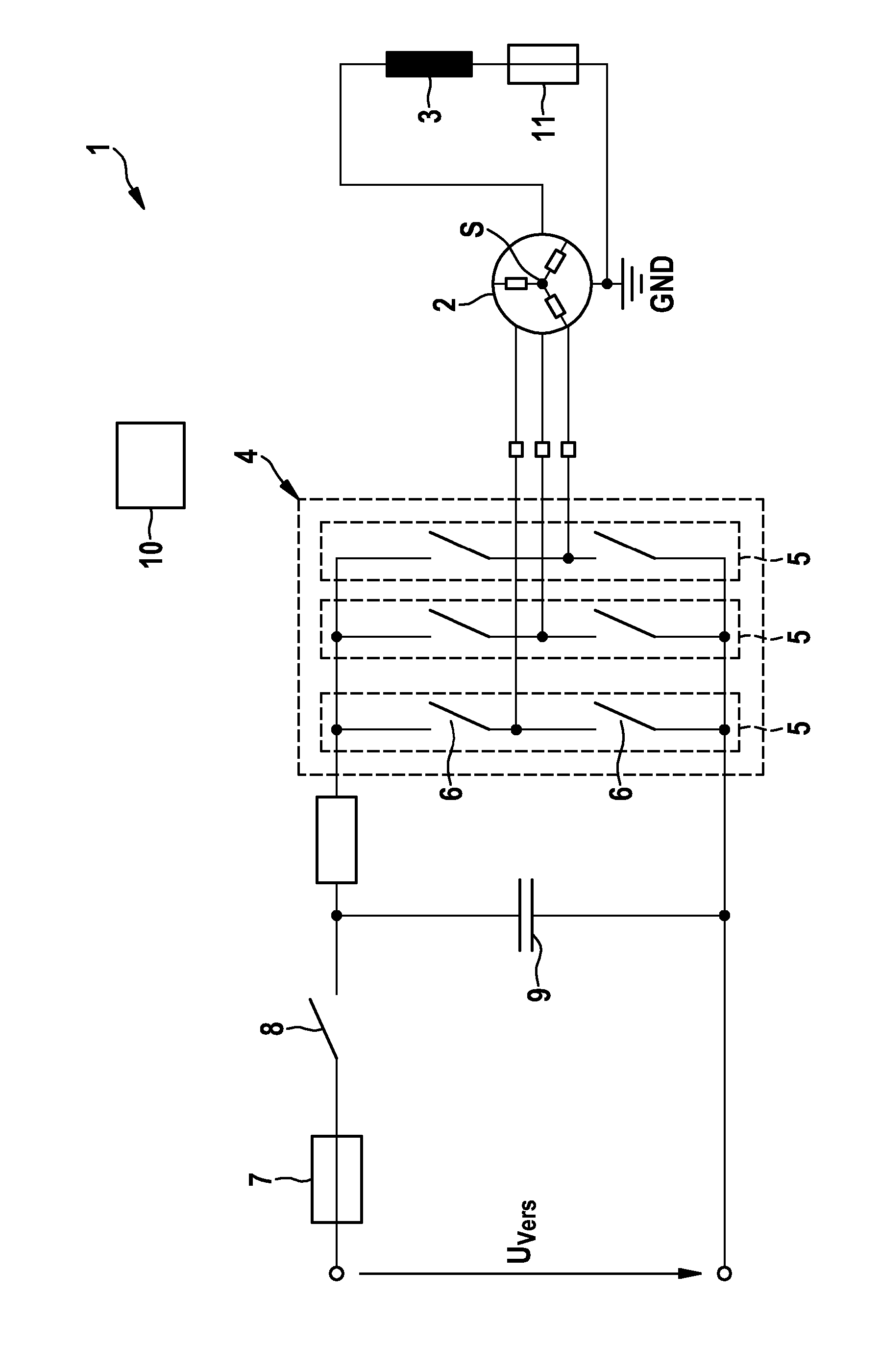
[0032] figure 1 A motor system 1 is shown with an electric machine 2 , which in this case has a three-phase design. The electric machine 2 has a stator structure with three phase conductors which are connected to each other via a star point S in a star point circuit.

[0033] The (not shown) rotor of the electric machine 2 consists of a soft-magnetic material and is supplied with an excitation field via the stationary field winding 3 , which essentially performs the same function as the permanent magnets in the rotor of a synchronous electric machine. . The field winding 3 is usually formed inside the stator so that the field field penetrates into the rotor and is deflected there so that a magnetic field is formed in the air gap between the rotor poles of the rotor and the stator, which is used to drive the rotor.

[0034] In order to energize the current circuit formed by the field winding 3 , which is connected in the exemplary embodiment shown between the star connection ...


PUM


Abstract

The invention relates to an electrically excited machine (2), in particular for use in a steering system of a motor vehicle, comprising: a stator with a stator winding having multiple phases; an exciter winding (3) which is arranged so as to couple an excitation magnetic field into a rotor that is movably disposed relative to the rotor so that a magnetic field is generated in an air gap between the stator and the rotor; and an exciting circuit having a fuse (11) which is automatically triggered in the event of an overcurrent.

Description

technical field [0001] The invention relates to electric machines, in particular electrically excited electric machines such as, for example, hybrid-excited or externally excited machines. The invention relates in particular to electrically excited electric machines used in steering systems and in particular to measures for reducing braking torques occurring in the event of a fault. Background technique [0002] Externally-excited or hybrid-exited electric machines require two additional electrical contacts for the field windings compared to permanent-magnet-excited machines. The field winding usually has to be actuated by means of its own control unit, field circuit. [0003] Alternatively, the field winding can also be energized via a drive circuit that operates the phase conductors of the electric machine. In this case, the field winding is connected between a star point via which the phase conductors of the electric machine are connected to one another and ground poten...

Claims


Application Information

Patent Timeline
Patent Type & Authority Applications(China)
IPC IPC(8): H02P29/02H02H7/06H02H7/08H02M7/48H02K19/12H02K11/00
CPCH02H7/0805H02K11/0057H02H7/0833H02K19/12H02K11/27H02H7/06H02H7/08H02K11/00H02P29/02
Inventor M.诺伊布格V.里格
Owner ROBERT BOSCH GMBH
Why Eureka
Try Eureka