
Dual-belt synchronous clamping conveying device

A clamping conveying and conveyor belt technology, applied in the direction of conveyors, transportation and packaging, etc., can solve the problems of unusable contact materials, unsuitable for highly floating materials, and reduced conveying volume, so as to achieve easy automation and centralization Control, realize automation and centralized control, flexible and reliable automatic tensioning mechanism

Active Publication Date: 2014-03-12
AEROSUN CORP
View PDF7 Cites 1 Cited by
  • Summary
  • Abstract
  • Description
  • Claims
  • Application Information

AI Technical Summary

Problems solved by technology

However, it is difficult for U-shaped or V-shaped belts to achieve an inclination angle of more than 30°, and the running speed will be limited due to the reduction of the loading section, and the conveying volume will be reduced.
Although the tubular tape can reach an inclination angle of more than 45°, the transportation volume is small and the cost increases
[0004] The search found that the Chinese patent application with the application number of 200710053814.1 disclosed a belt conveyor with a large inclination on the ordinary belt. This machine is equipped with a group of pressure belts in parallel above the conveyor belt. Since the position of the belt is fixed, the height of the conveyed material is high. Restricted, cannot be used for highly floating material conveying
The Chinese patent application with the application number 201110299130.6 discloses a large-inclination conveyor for conveying by means of strip-shaped protruding conveyor belts at intervals on the surface. Although this machine can convey bulk materials or block materials, it cannot be used for length Associated material greater than the spacing of the strips

Method used


Image

  • Dual-belt synchronous clamping conveying device
  • Dual-belt synchronous clamping conveying device
  • Dual-belt synchronous clamping conveying device

Examples


Embodiment 1

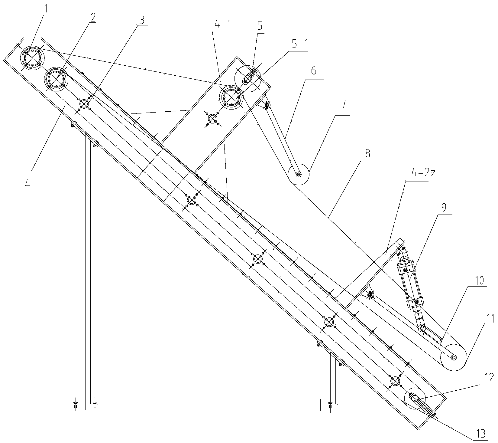
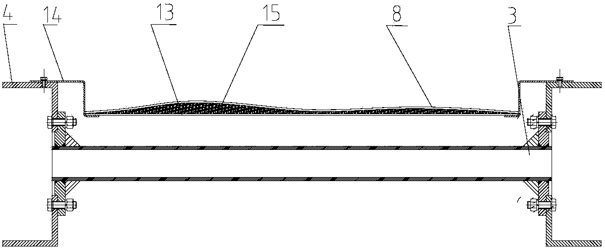
[0018] The dual-belt synchronous clamping and conveying device of this embodiment is as figure 1 and figure 2 As shown, the inclined frame 4 is composed of two channel steel side plates supported on the legs and connected by connecting rods 3 at intervals, and the inner sides of the two side plates are respectively fixed with a Z-shaped section plate whose lower edge is hooked on the edge of the lower conveyor belt 13 14. The upper end and the lower end of the frame 4 support the drive roller 2 and the pull-down tension roller 12 respectively. The driving roller 2 and the pull-down tension roller 12 are surrounded by a lower conveyor belt 13 . An upper frame 4-1 and a lower frame 4-2 perpendicular thereto extend from the upper part and the lower part of the frame 4 respectively. A driven roller 1 is also supported on the driving roller 2 of the frame 4, a synchronous driving roller 5-1 is supported on the upper frame 4-1, and a swing bar 6 with a floating roller 7 is insta...


PUM


Abstract

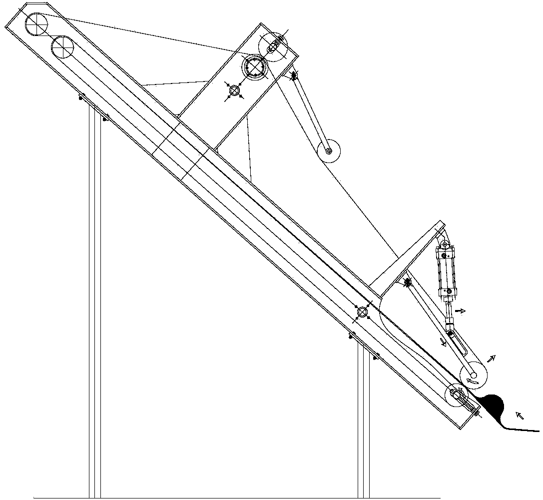
The invention relates to a dual-belt synchronous clamping conveying device, and belongs to the technical field of material conveying. The device comprises an oblique frame for supporting a driving roller and a pull-down tension roller, wherein a lower layer conveying belt is wound on the driving roller and the pull-down tension roller; an upper framework and a lower framework extend out of the frame; a driven roller is further supported on the driving roller of the frame; a synchronous driving roller is supported on the upper framework; a swinging rod of which the lower end is provided with a floating roller is hinged to the upper framework; a slide rail swinging rod of which the lower end is provided with a gravity roller is hinged to the lower part of the lower framework; the upper end of a bilateral cylinder is hinged to the upper end of the lower framework; the lower end of the bilateral cylinder and the slide rail extending along the length direction of the slide rail swinging rod construct a moving pair; an upper layer conveying belt is wound on the driven roller, the synchronous driving roller and the gravity roller; the floating roller is arranged on the upper layer conveying belt. According to the dual-belt synchronous clamping conveying device, stable and continuous conveying can be realized under the condition of large inclination angle, and a material inlet can float along with a shape to adapt to the height change; moreover, an automatic tensioning mechanism is flexible and reliable, materials are prevented from falling off, and automation and centralized control are realized easily.

Description

technical field [0001] The invention relates to a conveying device, in particular to a double-belt synchronous clamping conveying device, which belongs to the technical field of material conveying. Background technique [0002] The known conveying mechanism usually consists of a conveyor belt, a driving roller, a tensioning device, a braking device and the like. The conveyor belt is looped on the driving roller, and the driving roller drives the conveyor belt to move by the friction between the driving roller and the conveyor belt. In order to increase the friction between the driving roller and the conveyor belt and ensure the stable operation of the device to avoid slipping, a tensioning device is usually used to tighten the conveyor belt to increase the pressure between the roller and the conveyor belt and increase the friction. [0003] When the traditional conveyor only relies on friction to convey, the inclination angle is only allowed in the range of 0°-20°. If you ...

Claims


Application Information

Patent Timeline
IPC IPC(8): B65G15/16
Inventor 张驰孙强孙广仁
Owner AEROSUN CORP
Learn More