
Automatic water feeding device of barreled water

A technology for automatic water filling and bottled water, which is applied in hoisting devices, hoisting devices, etc., can solve problems such as flow fluctuations, inflow, and water filling failures, and achieve safe and reliable energy consumption, simple control system, and small motor power Effect

Inactive Publication Date: 2014-03-12
SHANGHAI UNIVERSITY OF ELECTRIC POWER
View PDF6 Cites 16 Cited by
  • Summary
  • Abstract
  • Description
  • Claims
  • Application Information

AI Technical Summary

Problems solved by technology

Among the existing patents, the patents on the automatic water supply device for bottled water include: an electric controllable lifting water dispenser water exchange device; a screw lifting and tumbling water dispenser automatic water exchange mechanism; a synchronous belt lifting water dispenser automatic loading system, etc. , but these patents have problems such as excessive overturning of the bottled water when filling water, and unsafe conditions
In addition, there are also studies on the indirect water feeding method of the water dispenser, such as pumping the water in the water dispenser into the drinking cup through water pump or suction with a vacuum pump, but this method will cause air to flow in from the mouth of the bucket when water is absorbed, causing the water to go up. Water failure, when used at the same time, the flow is easy to fluctuate, difficult to control, leakage and so on

Method used


Image

  • Automatic water feeding device of barreled water
  • Automatic water feeding device of barreled water
  • Automatic water feeding device of barreled water

Examples


Embodiment Construction

[0013] The present invention will be further described below in conjunction with the accompanying drawings and embodiments.

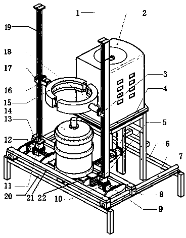
[0014] Such as figure 1 As shown, the bottled water automatic filling device of the present invention is made up of three major parts of mechanical system, power system and control system.

[0015] Mechanical system and power system include lifting column a1, water dispenser 2, lifting slider a3, longitudinal drive motor 4, lift drive motor a5, bracket 6, longitudinal guide rail 7, longitudinal guide rail slider 8, transverse drive motor a9, transverse guide rail slide Block a10, horizontal guide rail slider b11, horizontal driving motor b12, lifting driving motor b13, bottled water 14, grasping mechanism 15, rotating driving motor 16, lifting slider b17, limit stopper 18, lifting column b19, bracket base 20, support cross bar 21, barreled water seat 22.

[0016] The lifting slider, the horizontal guide rail slider and the barreled water seat are resp...


PUM


Abstract

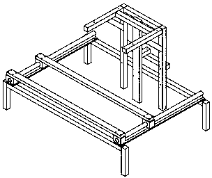
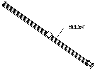
The invention relates to an automatic water feeding device of barreled water. A high frame on the rear portion of a support is provided with a water dispenser, and the two sides of the support are provided with longitudinal guide rails. The longitudinal guide rails are fixed on a support base and connected with a support cross bar through longitudinal guide rail sliding blocks. A longitudinal drive motor and a longitudinal ball screw are connected between the support base and the rear portion of the support. The longitudinal ball screw is connected with a barreled water base through a nut pair, and the two ends of the barreled water base are connected with a horizontal guide rail sliding block a and a horizontal guide rail sliding block b respectively through screw and nut pairs. The horizontal guide rail sliding block a and the horizontal guide rail sliding block b are connected with a horizontal drive motor a and a horizontal drive motor b respectively. Lifting stand columns are connected to the horizontal guide rail sliding block a and the horizontal guide rail sliding block b through a lifting drive motor a and a lifting drive motor b respectively. The lifting stand columns are connected with a grasping mechanism through lifting sliding blocks, and a rotation drive motor is connected between the lifting sliding block b on the lifting stand column b and the grasping mechanism. A limiting stop block is connected between the lifting sliding block a on the lifting stand column a and the grasping mechanism.

Description

technical field [0001] The invention relates to an automatic water supply device for bottled water, which is especially suitable for the automatic water supply device used in occasions such as homes and offices. Background technique [0002] The use of bottled water is becoming more and more common now. In big cities, the proportion of households using bottled water exceeds 80%, and almost all office buildings and schools use bottled water. It is often found that feeding water to the water dispenser is a cumbersome thing, especially for the old, weak, sick, disabled, and women. According to investigation, also there is not a kind of bottled water automatic water supply device in the market now. Among the existing patents, the patents on the automatic water supply device for bottled water include: an electric controllable lifting water dispenser water exchange device; a screw lifting and tumbling water dispenser automatic water exchange mechanism; a synchronous belt lifting ...

Claims


Application Information

Patent Timeline
Patent Type & Authority Applications(China)
IPC IPC(8): B66F19/00
Inventor 冯巧波罗毅白羡文吴江
Owner SHANGHAI UNIVERSITY OF ELECTRIC POWER
Learn More