Rolling rotor compressor oblique vane groove structure

A rolling rotor type, blade groove technology, applied in the field of blade groove structure, can solve problems such as suboptimal, and achieve the effects of improving work reliability, improving efficiency, and reducing the possibility of wear and tear

Active Publication Date: 2016-09-28
SHANGHAI HITACHI ELECTRICAL APPLIANCES CO LTD
View PDF6 Cites 0 Cited by
  • Summary
  • Abstract
  • Description
  • Claims
  • Application Information

AI Technical Summary

Problems solved by technology

This asymmetric load characteristic determines that the symmetrical traditional structure is not optimal in design.

Method used


Image

  • Rolling rotor compressor oblique vane groove structure
  • Rolling rotor compressor oblique vane groove structure
  • Rolling rotor compressor oblique vane groove structure

Examples


Embodiment Construction

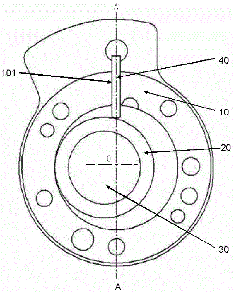
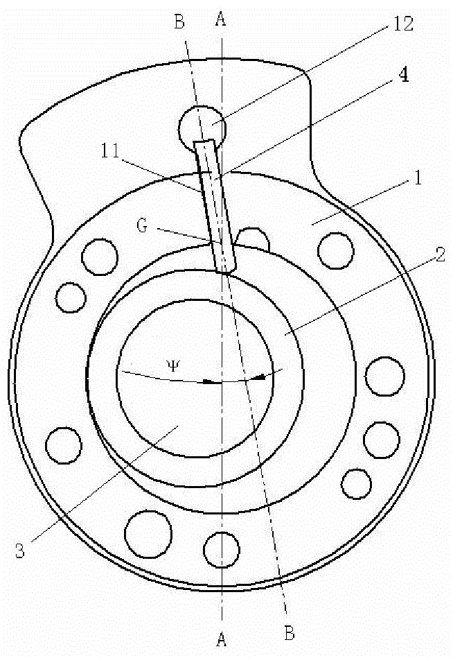
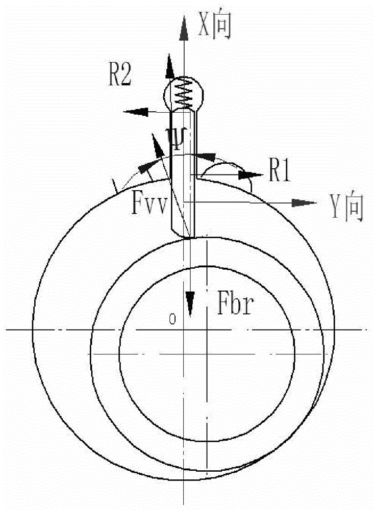
[0013] see figure 2 The oblique vane groove structure of the rolling rotor compressor includes a cylinder 1, a piston 2, a crankshaft 3, and a vane 4, wherein the cylinder 1 is provided with a vane groove 11 that can slide in the groove and closely fits the piston 2 and the cylinder 1 Connected guide seat 12. The vane groove rotates counterclockwise at an angle around the inner diameter of the cylinder and the intersection point G of the centerline AA of the original vane groove passing through the center O of the cylinder on the inner wall of the cylinder, forming an angle that is inclined relative to the centerline AA of the original vane groove, that is, the center The line is the blade groove 11 of BB, and the inclination angle is Ψ, Ψ is not greater than 22°. Preferably, the inclination angle Ψ is between 5° and 15°. The guide seat 12 is located on the vane slot 11 in a communication manner. And comprise the spring that is installed in its cylindrical inner hole, beca...


PUM


Abstract

A rolling rotor compressor with an oblique vane groove structure, the compressor includes a cylinder, a piston, a crankshaft and vanes. The cylinder is provided with a vane groove and a guide seat. The vane groove is rotated counterclockwise at an angle based on the intersection point of the inner diameter of the cylinder and the center line of the original vane groove passing through the center of the cylinder on the inner wall of the cylinder to form a center relative to the original blade groove. For linearly inclined blade grooves, the inclination angle Ψ is greater than 0° and less than 22°. The present invention is an asymmetrical blade motion structure set for the asymmetrical load of the traditional compressor operating within 0~360°, which can greatly reduce the contact force between the blade and the blade groove of the cylinder and the tip of the piston, thereby reducing the pressure of the blade groove and the tip of the blade. And the friction loss of the eccentric part, improve the efficiency of the compressor; at the same time improve the force of the blade. After the present invention is used on a rotary compressor, its input power drops by up to 1.0%, and its efficiency is significantly improved; the side support reaction force of the blades drops by up to 17%, and the reduction in wear of the blades and blade grooves improves the working reliability.

Description

technical field [0001] The invention relates to a rolling rotor compressor, in particular to a blade groove structure of the rolling rotor compressor. Background technique [0002] For rolling rotor compressors, the mechanical friction loss accounts for about 30% to 40% of the total power loss of the compressor during operation, and the friction loss caused by the blade groove, blade tip and eccentric part accounts for about 30% to 40% of the total mechanical friction loss. It is an important way to improve the efficiency of the compressor to reduce the friction loss at these places. At the same time, blades and blade slots are also one of the most prone to work reliability problems due to harsh stress conditions. [0003] The centerline AA′ of the vane slot (also known as the original vane slot) of the traditional rolling rotor compressor cylinder passes through the center O of the cylinder, such as figure 1 shown. When the piston 20 in the cylinder 10 follows the eccent...

Claims


Application Information

Patent Timeline
Patent Type & Authority Patents(China)
IPC IPC(8): F04C29/00F04C18/356
Inventor 沈建芳
Owner SHANGHAI HITACHI ELECTRICAL APPLIANCES CO LTD
Why Eureka
Try Eureka