Light unit for a motor vehicle

A technology for lighting units and motor vehicles, which is applied to vehicle lighting systems, lighting devices, fixed lighting devices, etc., can solve the problems of difficulty in combining incandescent lamps and light conductor optical devices, etc.

Inactive Publication Date: 2014-03-12
HELLA KG HUECK & CO
View PDF7 Cites 5 Cited by
  • Summary
  • Abstract
  • Description
  • Claims
  • Application Information

AI Technical Summary

Problems solved by technology

The disadvantage of incandescent lamps is that they have a considerable size and adjacent parts such as the chamber walls or reflector surfaces of the functional chamber must be kept at a relatively large distance from the incandescent lamp for thermal reasons
Furthermore, it is disadvantageous that incandescent lamps are very difficult to combine with light guide optics and can only be used with larger light guides
The disadvantage of LEDs is that they are small point light sources

Method used


Image

  • Light unit for a motor vehicle
  • Light unit for a motor vehicle
  • Light unit for a motor vehicle

Examples


Embodiment Construction

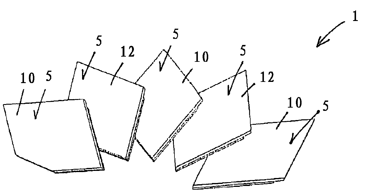
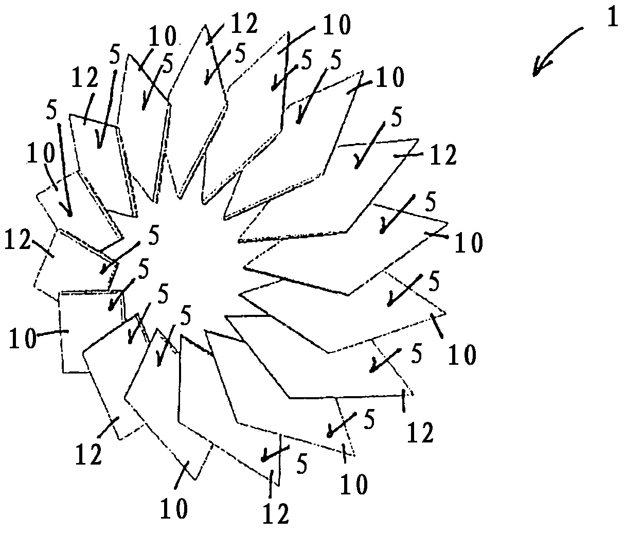
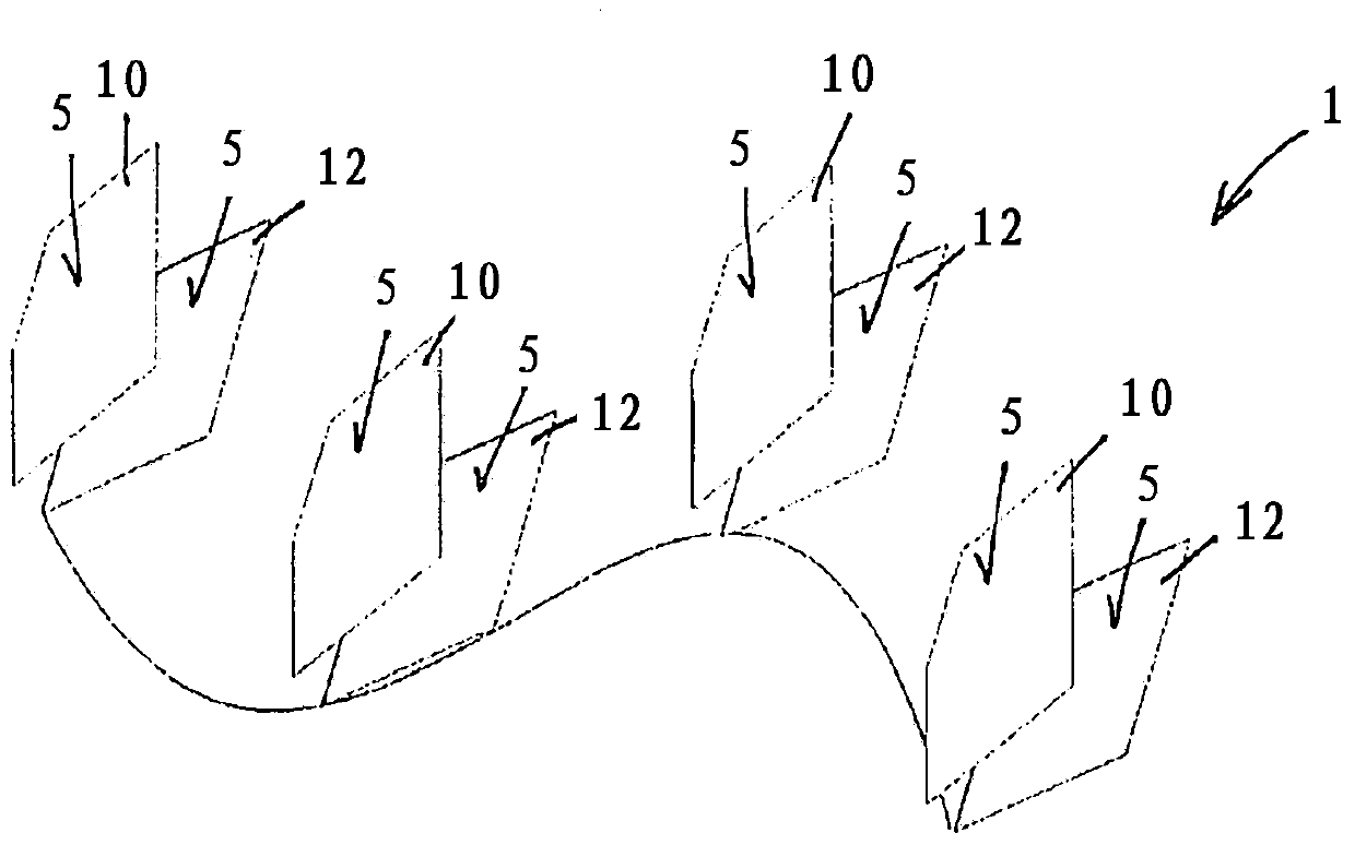
[0028] exist figure 1 A first OLED element 10 and a second OLED element 12 are shown in , which partially overlap and form the luminous area 5 . The size and shape of the first OLED element 10 and the second OLED element 12 can be freely selected in order to take into account, for example, the stylistic and construction-space boundary conditions of a predetermined rear light or headlight for which a signaling function is to be implemented. In this way, the OLED elements 10 , 12 can be embodied circularly, squarely, rectangularly, triangularly, hexagonally, octagonally, trapezoidally or with a free-form contour. If the first OLED 10 and the second OLED 12 are specified with respect to shape and size, the shapes can be arranged side by side in multiples in order to achieve the desired shape. In this case, the shape and size are designed and coordinated in such a way that the desired, best possible, homogeneous outer shape of the OLED arrangement can be achieved. exist figure...


PUM


Abstract

A light unit for a motor vehicle with an illuminated area through which visible light can be emitted. The illuminated area is formed by a first and a second planar OLED-element and the first OLED-element can be controlled independent from the second OLED-element, thus a segmenting of the illuminated area occurs.

Description

technical field [0001] The invention relates to a lighting unit for a motor vehicle according to the preamble of claim 1 , which has a lighting unit. Background technique [0002] It is known to use lighting units in vehicles, especially headlights and taillights. Here, two common light emitting devices are used. On the one hand, an incandescent lamp is used as a standard light source. Incandescent lamps are available in different shapes, sizes and with different luminous fluxes, so that the right incandescent lamp can be selected for any application. Generally, incandescent lamps generate white light, but also emit colored, in particular yellow or red, light through coatings on the glass bulb or through colored additional glass panes or outer panes. On the other hand light emitting diodes can be used. Light emitting diodes are constructed from multiple layers of semiconductor material. When the diode is driven in the forward direction, light is generated in the thin la...

Claims


Application Information

Patent Timeline
Patent Type & Authority Applications(China)
IPC IPC(8): F21S8/10F21V13/00F21Y105/00
CPCF21S48/115F21S48/217F21S43/145F21S41/141
Inventor C·邦根施托克C·霍曼M·米格A·普尔斯T·菲尔埃格
Owner HELLA KG HUECK & CO
Why Eureka
Try Eureka