Visualization testing method and device for granular material mechanics experiment

A granular material and mechanical experiment technology, applied in the field of granular material mechanical experiment visualization test method and its testing device, to achieve the effects of high precision, reliable use, and convenient installation

Inactive Publication Date: 2014-03-12
SOUTH CHINA UNIV OF TECH
View PDF0 Cites 33 Cited by
  • Summary
  • Abstract
  • Description
  • Claims
  • Application Information

AI Technical Summary

Problems solved by technology

[0005] At present, there is no relevant report on the visualization of the internal mesoscopic mechanical properties of particles in China. The proposed method and test device can provide useful reference for future related research methods.

Method used


Image

  • Visualization testing method and device for granular material mechanics experiment
  • Visualization testing method and device for granular material mechanics experiment
  • Visualization testing method and device for granular material mechanics experiment

Examples


Embodiment 1

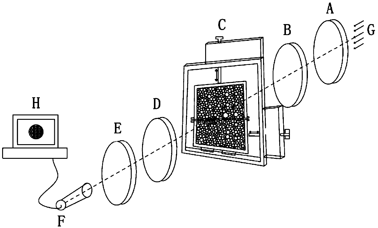
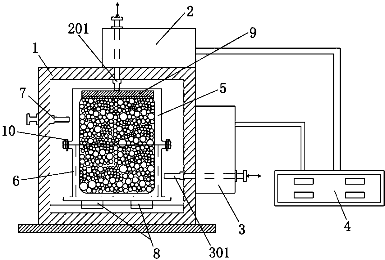
[0032] The method for visual testing of granular material mechanics experiments in the present invention is to first process millimeter-scale particles (the smallest size can be up to 2mm, its shape is spherical, cylindrical, elliptical cylindrical, polygonal or irregular), put it into the visual loading device that can apply compressive / shearing load, and then turn on the light source G, so that the light emitted by the light source goes along the Polarizer A, 1 / 4 wave plate B, visualization loading device C, 1 / 4 wave plate D, analyzer E, camera F spread, and ensure that the light emitted by light source G propagates to millimeter-sized particles, specifically as figure 1As shown, according to the corresponding experimental requirements (simulation of various common soil mechanics tests, such as compression, shear, stress arch, foundation load under rigid or flexible foundation, etc.), the millimeter-sized particles are subjected to compressive load or shear load, or The appl...

Embodiment 2

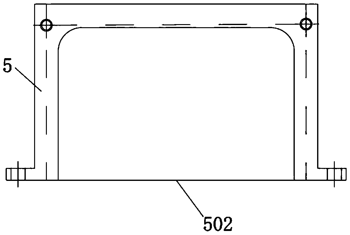
[0038] see Figure 7 As shown, what is different from Example 1 is that this embodiment puts two rectangular steel plates 11, 12 in the described granular material sample box (the rectangular steel plates can be selected from various sizes, and the distance between the two steel plates depends on The size of the steel plate is adjusted) to simulate a fixed pile. Then fill up the granular material around the steel plate, the granular material is determined according to the selected slot spacing, and also put the granular material of the corresponding length from the top discharge port of the granular material sample box 5 on the visualization, in this implementation The granular material used in the example is also a photoelastic cylinder with a diameter of millimeters. Similarly, a large number of small cylinders are put into the granular material sample box with slender tweezers. Close to the wall of the visualization board, when the sample box of the granular material is fi...


PUM


Abstract

The invention discloses a visualization testing method and device for a granular material mechanics experiment. The method comprises the following steps: putting luminous millimeter-sized granules into a visualization loading device capable of applying a compression/shear load; starting a light source to propagate light emitted by the light source along a polarizer, a quarter-wave plate, the visualization loading device, a quarter-wave plate, an analyzer and a camera in sequence; and applying the compression load, the shear load or the combination of the compression load and the shear load to the granules according to corresponding experimental requirements. In a loading process, fringes which are alternately dark and bright are formed in an image acquired by the camera; according to a stress-optical law, the size change of the stresses at different positions in the millimeter-sized granules can be directly observed through the density of the fringes or the light intensity; and after the image acquired by the camera is processed, the stress distribution in granular media can be identified and metered, and the contact stress between the granules, the thickness and angle of shear bands in the granular media and the distribution and trend of mechanical chains can be visualized.

Description

technical field [0001] The invention relates to the technical field of testing, analysis and visualization of mechanical properties of granular materials, in particular to a visual testing method and testing device for mechanical experiments of granular materials. Background technique [0002] Geotechnical particulate matter is ubiquitous in nature, engineering construction and daily life, and the research on its mechanical properties and dynamic response has been carried out in academia for decades. In previous studies, rock and soil particles were generally assumed to be a continuum for analysis. Based on the classical elastic-plastic mechanics theory, people have developed many rock and soil macroscopic mechanical models, but none of them can fully and correctly express The constitutive equation for its stress-strain relationship. The reason is mainly because the assumption based on continuum is inconsistent with the discontinuous particle characteristics of rock and soi...

Claims


Application Information

Patent Timeline
Patent Type & Authority Applications(China)
IPC IPC(8): G01N3/02G01N3/08G01N3/24
Inventor 房营光谷任国侯明勋陈平
Owner SOUTH CHINA UNIV OF TECH
Why Eureka
Try Eureka