A linear continuously adjustable light attenuation unit

A dimming attenuation, straight-line technology, applied in the coupling of optical waveguides, etc., can solve the problems of power jump, reduce instrument reliability, increase insertion loss, etc., and achieve increased return loss, improved reliability, and increased insertion loss. reduced effect

Active Publication Date: 2016-04-13
THE 41ST INST OF CHINA ELECTRONICS TECH GRP
View PDF3 Cites 0 Cited by
  • Summary
  • Abstract
  • Description
  • Claims
  • Application Information

AI Technical Summary

Problems solved by technology

[0004] The traditional optical attenuation unit has the following disadvantages: On the one hand, due to the use of two filters, the traditional optical attenuation unit will inevitably produce power jumps when performing 10dB step shifts. For some test occasions, this situation is unacceptable; on the other hand, the traditional optical attenuation unit needs two filters and two motors, which not only increases the insertion loss, but any problem with any one of the filters or motors will affect the performance of the attenuator. normal operation, reducing the reliability of the instrument

Method used


Image

  • A linear continuously adjustable light attenuation unit
  • A linear continuously adjustable light attenuation unit
  • A linear continuously adjustable light attenuation unit

Examples


Embodiment 1

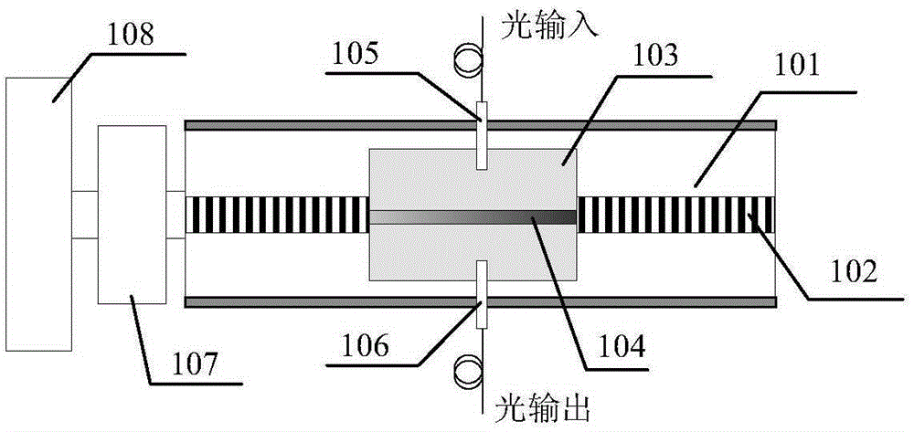
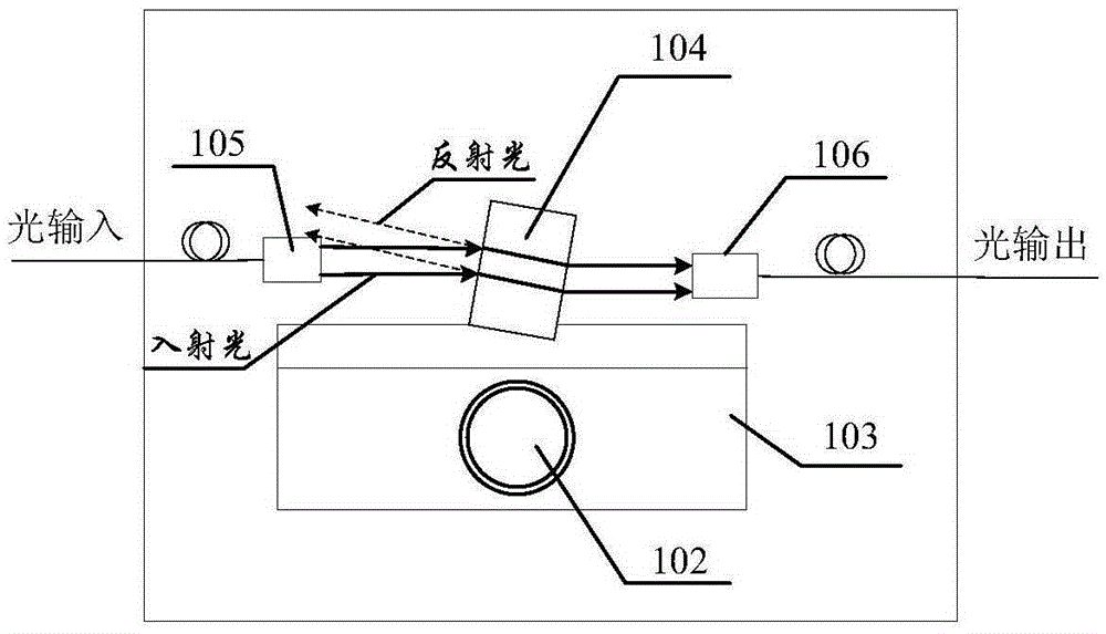
[0022] Such as Figure 2-Figure 3 As shown, the present invention is mainly composed of a linear module 101 , a strip filter 104 , a fiber collimator 105 , a fiber collimator 106 , a motor 107 and a photoelectric encoder 108 . The fiber collimator 105 and the fiber collimator 106 are respectively arranged in the middle of the two corresponding frames of the linear module 101 and aligned, and the linear module 101 is provided with a precision lead screw 102 and a slider 103, The slider 103 is installed on the precision screw 102, and the precision screw 102 drives the slider 103 to make precise reciprocating motion on the linear module 101 by rotation, and the strip filter 104 is fixed on the slider 103 Above, one end of the motor 107 is connected to the photoelectric encoder 108, and the other end is connected to the precision lead screw 102. The rotation of the motor 107 drives the rotation of the precision lead screw 102, thereby driving the strip filter 104 in the optical f...


PUM


Abstract

The invention provides a linear type continuous variable optical attenuation unit which mainly consists of a linear module, a strip-shaped optical filter, two optical fiber collimators, a motor and a photoelectric encoder, wherein the two optical fiber collimators are respectively arranged at middle positions of two corresponding frames of the linear module and are aligned with each other; a precision lead screw and a slide block are arranged on the linear module; the strip-shaped optical filter is fixed on the slide block of the precision lead screw; one end of the motor is connected with the photoelectric encoder, and the other end of the motor is connected with the precision lead screw; the strip-shaped optical filter is driven to move between the two optical fiber collimators by utilizing rotation of the motor, the position of the strip-shaped optical filter is encoded by utilizing the photoelectric encoder, and the strip-shaped optical filter is accurately positioned, so that continuous and accurate attenuation of optical power is realized. By adoption of the scheme, the insertion loss of the novel optical attenuation unit system is reduced, and the reliability of the system is improved; the return loss of the optical attenuation unit is increased, and a front-loading light path is protected.

Description

technical field [0001] The invention belongs to the technical field of adjustable light attenuation, and in particular relates to a linear continuously adjustable light attenuation unit. Background technique [0002] Adjustable optical attenuator is one of the commonly used instruments in optical fiber communication systems. Its main function is to accurately attenuate the intensity of optical signals. It is widely used in teaching experiments, R&D and production testing of optical devices, and construction and maintenance of optical fiber communication networks. The optical attenuation unit is the core component of the adjustable optical attenuator, and the quality of its design will directly affect the level of various performance indicators of the adjustable optical attenuator. [0003] Traditional optical attenuation units such as figure 1 As shown, the incident light is collimated by the fiber collimator, attenuated by two circular filters, and finally enters the outpu...

Claims


Application Information

Patent Timeline
Patent Type & Authority Patents(China)
IPC IPC(8): G02B6/26
Inventor 徐玉华魏石磊杭栋栋李宝瑞杨玥暄汪磊
Owner THE 41ST INST OF CHINA ELECTRONICS TECH GRP
Why Eureka
Try Eureka