High-speed automatic crimping machine for optical fiber insertion core

An optical fiber ferrule and crimping machine technology, which is applied in the coupling of optical waveguides and other directions, can solve the problems of complex overall structure design, low production efficiency, low crimping efficiency, etc. High connection efficiency

Active Publication Date: 2014-03-12
深圳市雅合科技有限公司
View PDF6 Cites 8 Cited by
  • Summary
  • Abstract
  • Description
  • Claims
  • Application Information

AI Technical Summary

Problems solved by technology

In the prior art, there are two ways to crimp the fiber ferrule. One is to use simple tooling for manual crimping, but the labor intensity is high and the production efficiency is low; the other is to use a special crimping machine to crimp the fiber ferrule. crimping, but the overall structure design of the existing crimping machine is complicated, and the maintenance cost is high. Although it can realize the automatic crimping of the optical fiber ferrule, it is usually intermittent crimping, and the crimping efficiency is low

Method used


Image

  • High-speed automatic crimping machine for optical fiber insertion core
  • High-speed automatic crimping machine for optical fiber insertion core
  • High-speed automatic crimping machine for optical fiber insertion core

Examples


Embodiment Construction

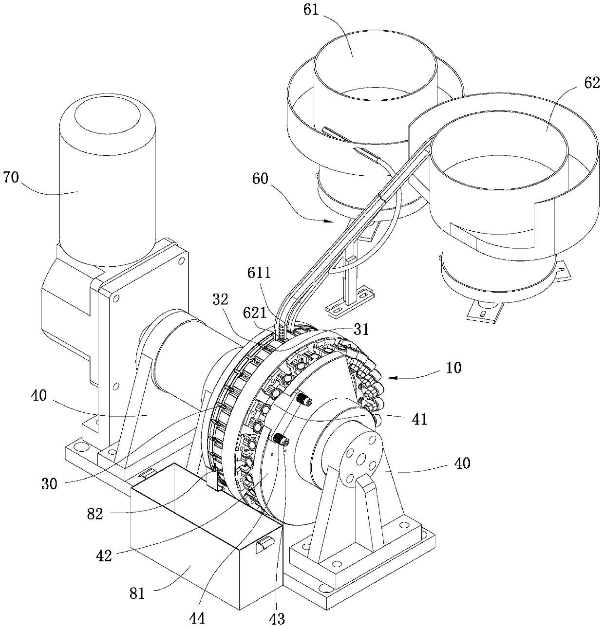
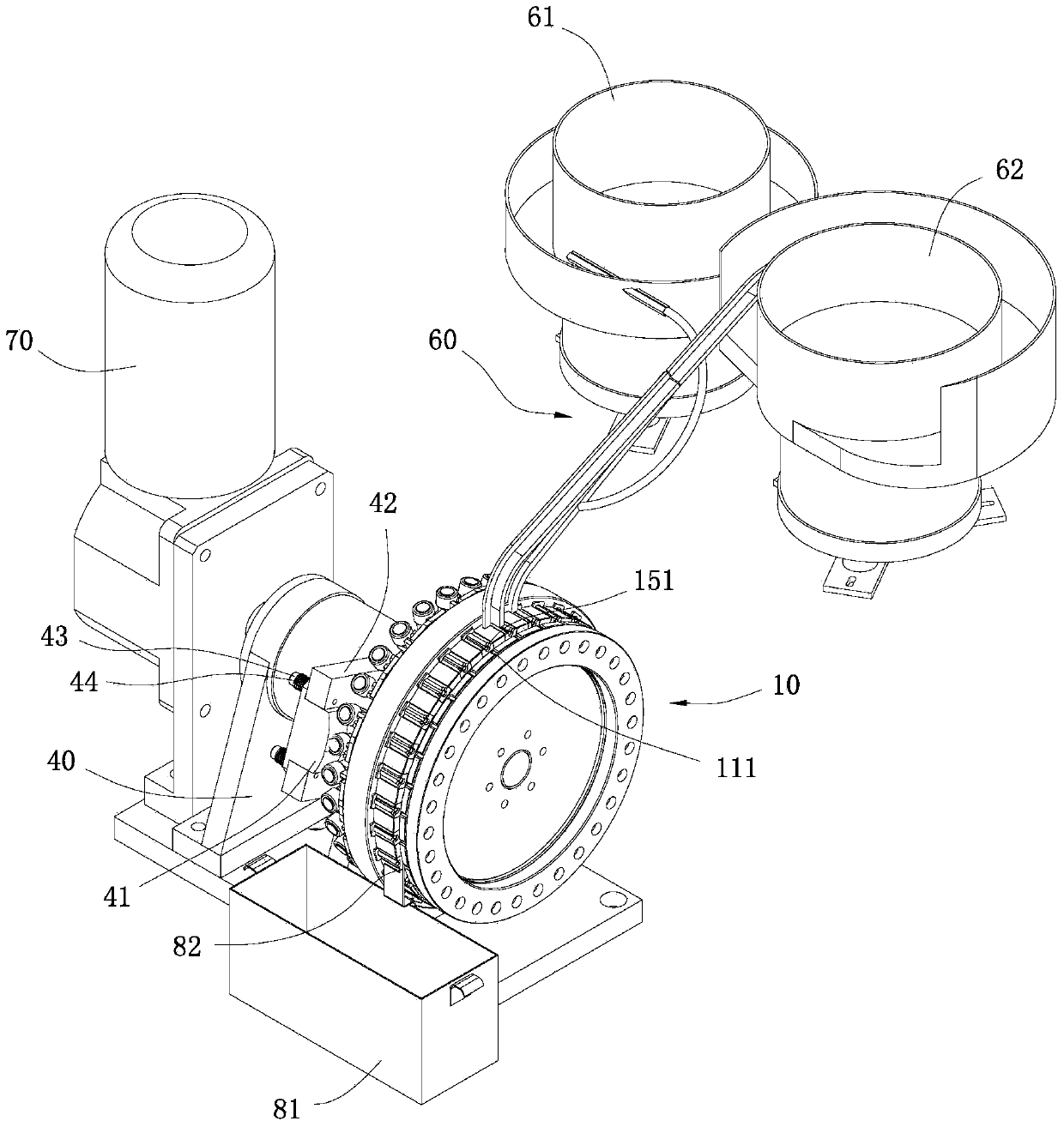
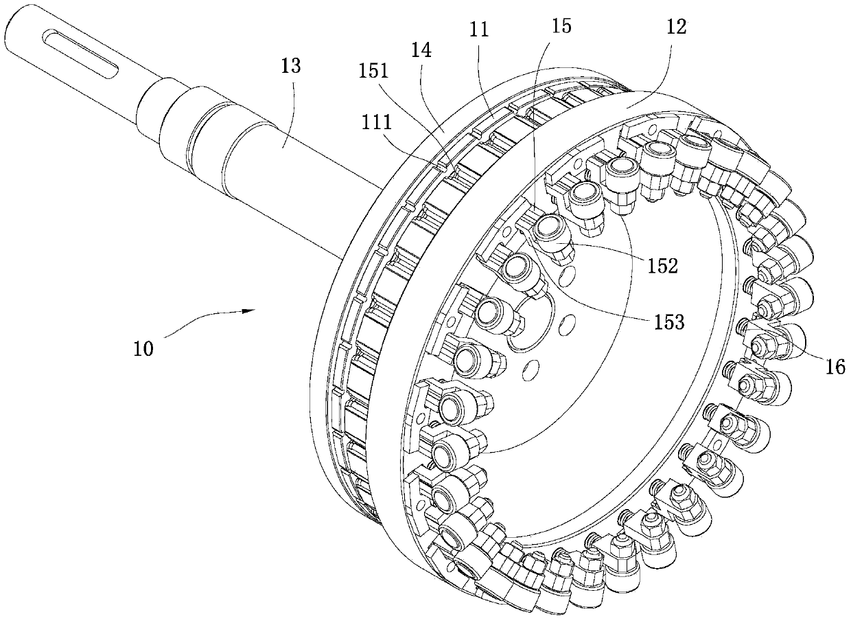
[0021] refer to Figure 1 to Figure 6 , an optical fiber ferrule high-speed automatic crimping machine of the present invention is used for crimping a metal tail handle 31 and a ceramic ferrule 32, comprising a support seat 40, a turntable body 10 horizontally arranged on the support seat 40, and a drive turntable body 10 The rotating driving device 70 and the feeding mechanism 60 are arranged at intervals along the circumferential direction on the outer circular end surface of the turntable body 10 with a plurality of accommodating grooves 111 for placing ceramic ferrules 32, and on the outer circular end surface of the turntable body 10 along the circumferential direction There are sliders 15 that are arranged side by side with each receiving groove 111 and can move axially along the turntable body 10 at intervals in the direction. At the end of each slider 15 facing the ceramic ferrule 32, there is a receiving notch 151 where the metal tail handle 31 can be placed. On the s...


PUM


Abstract

The invention discloses a high-speed automatic crimping machine for an optical fiber insertion core. The high-speed automatic crimping machine is used for crimping a metal tail handle and a ceramic insertion core and comprises a support base, a turntable body, a driving device and a material supplying mechanism; multiple containing slots for placing the ceramic insertion cores are arrayed at the outer circle end surface of the turntable body along the circumferential direction at intervals; sliders parallel with the containing slots are arranged at the outer circle end surface of the turntable body; a containing slot port for placing the metal tail handle is arranged at one end of each slider; a floating ejecting block is arranged at the outer edge end surface of one side, provided with the sliders, of the turntable body on the support base; the turntable body adopts a horizontal turntable structure; when the turntable body rotates, the other end of each slider sequentially passes and touches the floating ejecting block to be pushed so as to move towards the direction of the ceramic insertion core, so the ceramic insertion core is pressed into the metal tail handle to form the optical fiber insertion core, fast and continuous crimping is realized, the crimpling efficiency is high, the whole crimping machine is compact in structure, easy to control and lower in manufacturing cost.

Description

technical field [0001] The invention relates to the technical field of manufacturing optical fiber accessories, in particular to an optical fiber ferrule crimping machine. Background technique [0002] The fiber optic ferrule is composed of a ceramic ferrule and a metal tail handle. During assembly, the ceramic ferrule needs to be pressed into the inner hole of the metal tail handle. In the prior art, there are two ways to crimp the fiber ferrule. One is to use simple tooling for manual crimping, but the labor intensity is high and the production efficiency is low; the other is to use a special crimping machine to crimp the fiber ferrule. crimping, but the overall structure design of the existing crimping machine is complicated, and the maintenance cost is high. Although it can realize automatic crimping of optical fiber ferrule, it is usually intermittent crimping, and the crimping efficiency is low. Contents of the invention [0003] The technical problem to be solved b...

Claims


Application Information

Patent Timeline
Patent Type & Authority Applications(China)
IPC IPC(8): G02B6/38
Inventor 王胜玲
Owner 深圳市雅合科技有限公司
Why Eureka
Try Eureka