Charging tray type feeder, electronic component loading device and carrier transferring method

A technology of electronic components and feeders, applied in the direction of electrical components, electrical components, etc., can solve problems such as wrong transfer, and achieve the effect of preventing human errors and saving labor and working hours

Active Publication Date: 2014-03-12
PANASONIC INTELLECTUAL PROPERTY MANAGEMENT CO LTD
View PDF7 Cites 4 Cited by
  • Summary
  • Abstract
  • Description
  • Claims
  • Application Information

AI Technical Summary

Problems solved by technology

[0007] However, in the above-mentioned prior art, the transfer operation of the carrier is completed by the hands of the operator, but this operation requires a lot of man-hours and labor for the operator.
In addition, for example, when there is no significant difference in appearance between th

Method used


Image

  • Charging tray type feeder, electronic component loading device and carrier transferring method
  • Charging tray type feeder, electronic component loading device and carrier transferring method
  • Charging tray type feeder, electronic component loading device and carrier transferring method

Examples


Embodiment approach 1

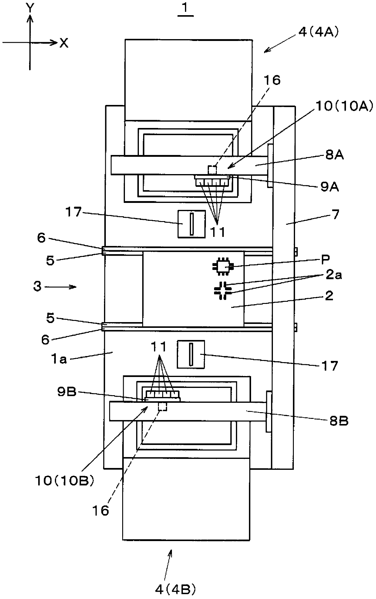
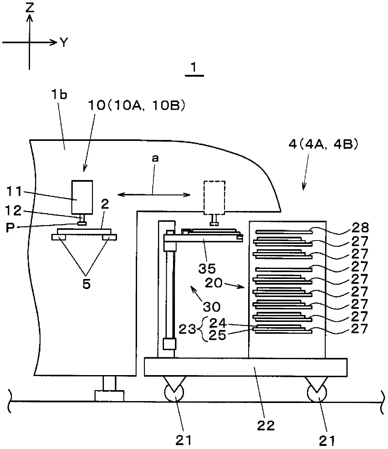
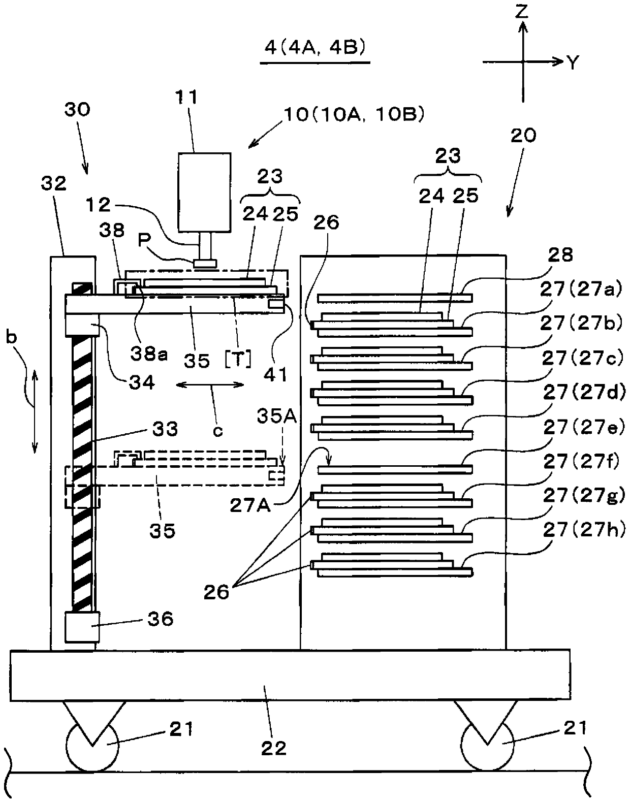
[0041] First, refer to figure 1 The electronic component mounting device according to Embodiment 1 will be described. The electronic component mounting device 1 is composed of an electronic component mounting device main body and a tray feeder 4 (4A, 4B). The substrate 2 is transported along the substrate transport direction, that is, the X direction, and positioned at the specified working position ( figure 1position of the substrate 2 shown), and the mounting head 10 ( 10A, 10B) as an electronic component mounting portion for mounting the electronic component P on the electrode 2 a of the substrate 2 positioned by the substrate conveying portion 3 ; The tray feeders 4 ( 4A, 4B) serve as component supply units and are respectively provided on both sides of the base 1 a facing in the Y direction perpendicular to the X direction, and supply electronic components P to the mounting head 10 . In addition, the electronic component mounting main body is composed of a cover member ...

Embodiment approach 2

[0087] Next, refer to Figure 14 The structure of the electronic component mounting apparatus 100 of this Embodiment 2 is demonstrated. In addition, the difference from the electronic component mounting device 1 of the first embodiment is only the tray feeder, and the same components as the electronic component mounting device 1 will be described using the same reference numerals. The tray feeder 400 constituting the electronic component mounting apparatus 100 is provided with a suction head 401 that can hold the carrier 23 moved to the component supply position [T] via the tray 24. The suction nozzle 401a for sucking and holding the electronic component P. The suction head 401 can be moved in the X and Y directions by a suction head moving mechanism not shown. In addition, the suction nozzle 401a can be moved in the Z direction by a suction nozzle raising and lowering mechanism not shown.

[0088] In addition, a shuttle 402 which has a horizontal surface on which the elect...


PUM


Abstract

The invention provides a charging tray type feeder, an electronic component loading device and a carrier transferring method, wherein carriers held on the faulty carrier holder of a carrier acceptor can be accurately are transferred to a desired carrier holder. Meanwhile, the carrier holding bench is moved to a place opposite to the carrier holder, so that the carriers are pulled out of the carrier holder. Then the carriers are transferred onto the carrier holding bench. After that, the carrier holding bench is driven to go up to be right facing a carrier temporary storage bracket, and then the carriers are transferred to the carrier temporary storage bracket. Afterwards, the carrier holding bench is driven to go down to be right facing the carrier holding bench and the carriers are drawn out of the carrier holding bench. Then the carrier holding bench is driven to go up to be right facing the carrier holder. Finally, the carriers are transferred to the carrier holder. Meanwhile, carriers, such as diet preparation data and the like, are held on the carrier holder.

Description

technical field [0001] The invention relates to a tray-type feeder, an electronic component mounting device, and a carrier transfer method in the tray-type feeder. Background technique [0002] In an electronic component mounting device, a tray feeder is known as one type of component feeder for supplying electronic components. This tray feeder includes a carrier storage body and a carrier moving unit, and the carrier storage body is provided with a plurality of vertically accommodating carriers consisting of trays accommodating electronic components and trays holding the trays. Carrier holder; the carrier moving unit pulls out the carrier from the carrier holder to move the carrier to a position where the electronic components contained in the carrier can be supplied to the head of the electronic component mounting device (for example, Patent Document 1 ,2). Among such tray-type feeders, there is known a tray-type feeder in which, from the viewpoint of improving the effic...

Claims


Application Information

Patent Timeline
IPC IPC(8): H05K13/02
Inventor 松村洋渡边真也纳土章
Owner PANASONIC INTELLECTUAL PROPERTY MANAGEMENT CO LTD
Why Eureka
Try Eureka