Photovoltaic module junction box hanging experiment device and method

A technology of photovoltaic modules and hanging junction boxes, which is applied in the direction of measuring devices, parts of electrical measuring instruments, instruments, etc., can solve problems such as inaccurate experimental results, increase experimental time, and increase the workload of experimenters, so as to ensure accuracy , save labor, save labor and labor time effect

Active Publication Date: 2014-01-08
YINGLI ENERGY CHINA
View PDF9 Cites 3 Cited by
  • Summary
  • Abstract
  • Description
  • Claims
  • Application Information

AI Technical Summary

Problems solved by technology

In the experiment of hanging the junction box, it is stipulated that the force acting on the junction box perpendicular to the junction box is 155.7N. If the photovoltaic module does not act on the junction box at the same horizontal plane, the force acting on the junction box is F=G×cosa
Therefore, the existing technology cannot fundamentally ensure that the component surfaces are on the same level, resulting in F<155.7N, resulting in inaccurate experimental results
[0004] In addition, in the above experiment, two experimenters are required to repeatedly lift the photovoltaic module out of the wet insulation pool, then lift the module to the pendant junction box test bench, and then lift the photovoltaic module from the pendant junction box test bench to the wet insulation pool, After the experiment is over, the experimenter has to remove the weight by hand, which increases the workload of the experimenter and also increases the experiment time.

Method used


Image

  • Photovoltaic module junction box hanging experiment device and method
  • Photovoltaic module junction box hanging experiment device and method
  • Photovoltaic module junction box hanging experiment device and method

Examples


Embodiment Construction

[0033] In order to make the object, technical solution and advantages of the present invention clearer, the present invention will be further described in detail below in conjunction with the accompanying drawings and embodiments. It should be understood that the specific embodiments described here are only used to explain the present invention, not to limit the present invention.

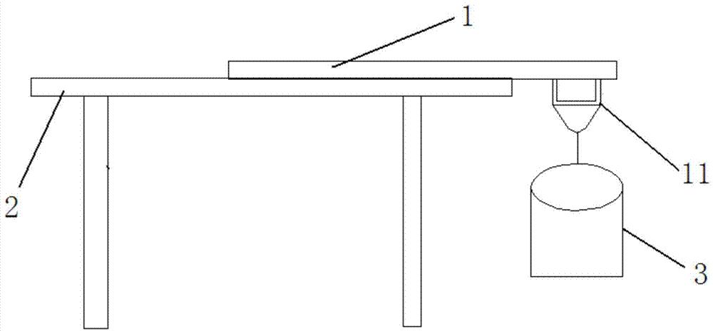
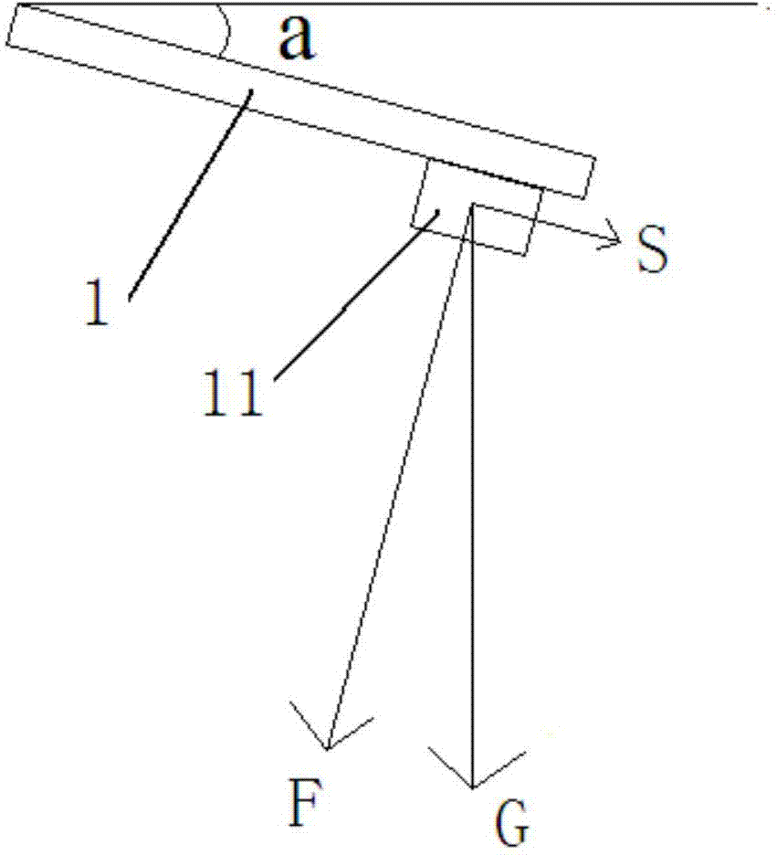
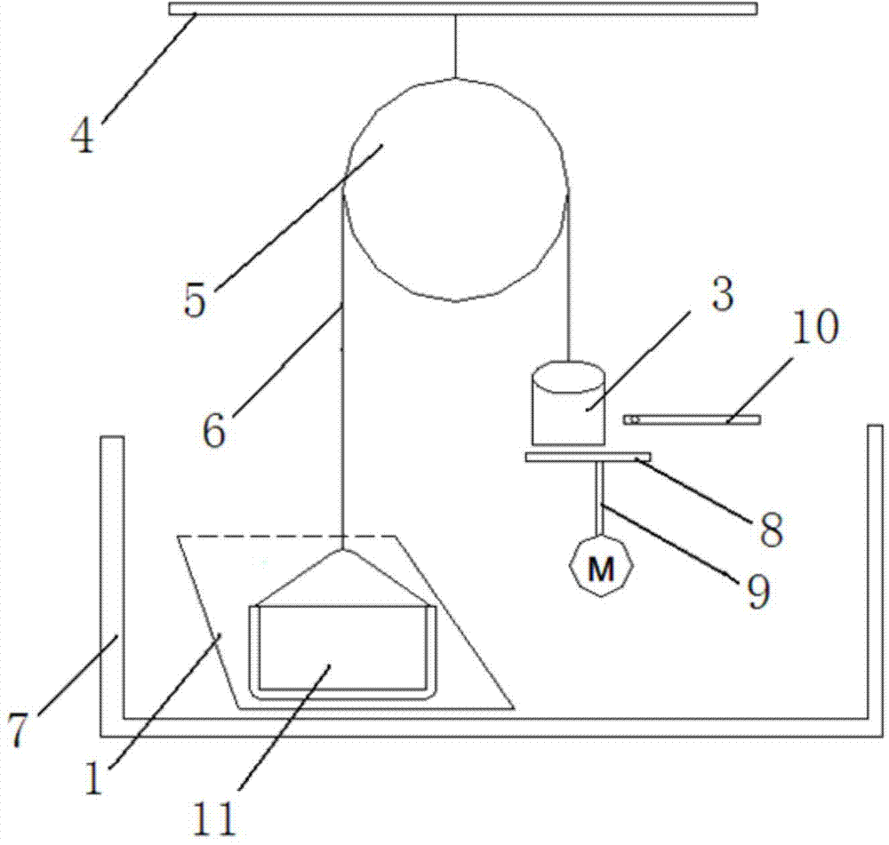
[0034] This embodiment provides a novel experimental device for photovoltaic modules, such as image 3 As shown, the experimental device mainly includes: a fixed bracket 4, a fixed pulley 5, a motor M, a test rope 6, a weight 3 and a control system for controlling the motor M (not shown in the figure).

[0035] Wherein, the fixing bracket 4 is arranged above the wet insulation test pool 7 used for the wet insulation test of the photovoltaic module. The fixed pulley 5 is fixed on the fixed bracket 4, the test rope 6 passes through the fixed pulley 5, one end is connected to the junction box 11 to b...


PUM


Abstract

The invention provides a photovoltaic module junction box hanging experiment device, which comprises a fixing support frame, a fixed pulley, a motor, a testing rope, a poise and a control system, wherein the control system is used for controlling the motor, the fixed support frame is arranged above a wet insulation testing pool, the fixed pulley is fixedly arranged on the fixing support frame, the testing rope passes through the fixed pulley, one end of the testing rope is connected with a junction box, the other end of the testing rope is connected with the poise, a supporting support frame is connected onto the motor, the supporting support frame is positioned under the poise, and a position limiting mechanism is arranged above the supporting support frame and is connected with a position limiting switch. A method for carrying out junction box hanging experiments by adopting the device comprises the following steps that one end of the testing rope is connected with the junction box, the poise is hung at the other end of the testing rope, an air switch is switched on, the motor starts to work when a time relay reaches the delay time, the position limiting switch is switched off when the supporting support frame upwards moves to the position limiting mechanism, the motor stops working, and the testing rope is disconnected from the junction box. The device and the method have the advantages that a photovoltaic module is always in the same plane in the experiment process, and the precision of experiment results is ensured.

Description

technical field [0001] The invention relates to the field of photovoltaic technology, in particular to an experimental device and method for hanging a junction box of a photovoltaic module. Background technique [0002] In the photovoltaic industry, after the first wet insulation test of photovoltaic modules, a hanging junction box test is required. Two experimenters cooperate to lift the modules out of the wet insulation test pool. Since the backplane and glass of the photovoltaic modules contain water, first Control the water for 40 seconds, and then lift the photovoltaic module to the hanging junction box test bench (it takes about 30 seconds). like figure 1 As shown, the component is placed horizontally on the test bench with the glass facing upwards, and one side of the junction box of the module protrudes from the test bench by more than 10cm. Fix the test rope on the junction box, and then hang a weight of 155.7N on the test bench. On the rope, the experimenter coun...

Claims


Application Information

Patent Timeline
Patent Type & Authority Applications(China)
IPC IPC(8): G01R1/02G01R31/12
Inventor 张江立
Owner YINGLI ENERGY CHINA
Why Eureka
Try Eureka