Mold with automatic part catcher

A feeder, automatic technology, applied in the direction of forming tools, manufacturing tools, metal processing equipment, etc., can solve the problems of low production efficiency and high labor intensity of workers, so as to improve production efficiency, reduce labor intensity, and solve the problem of manual feeding. effect of the problem

Inactive Publication Date: 2016-03-02
中山市镇丽塑胶五金制品有限公司
View PDF12 Cites 0 Cited by
  • Summary
  • Abstract
  • Description
  • Claims
  • Application Information

AI Technical Summary

Problems solved by technology

[0003] The purpose of this invention is to provide a mold with an automatic material catcher, which solves the problems of low production efficiency and high labor intensity of workers

Method used


Image

  • Mold with automatic part catcher
  • Mold with automatic part catcher
  • Mold with automatic part catcher

Examples


Embodiment Construction

[0014] Embodiments of the present invention will now be described with reference to the drawings, in which like reference numerals represent like elements.

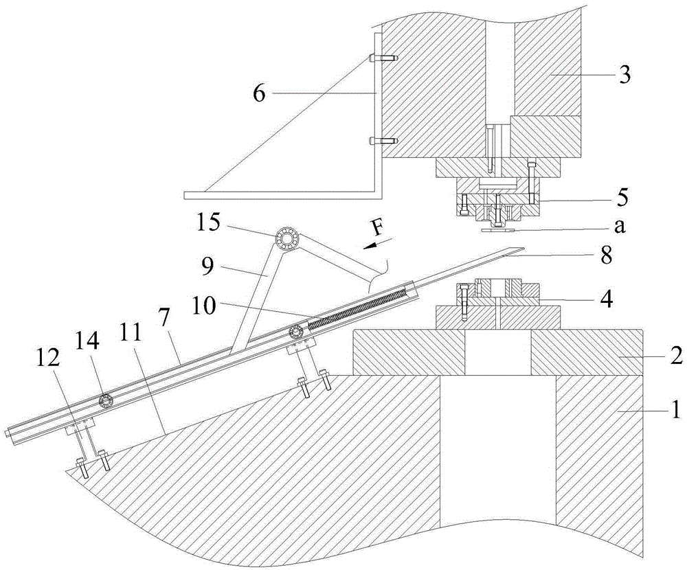
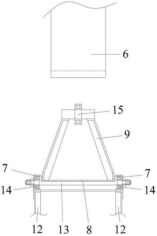
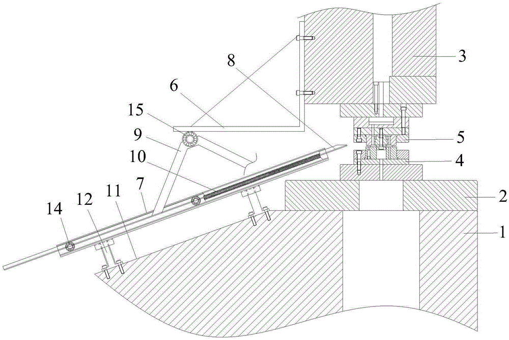
[0015] Please refer to Figure 1-3 , The mold with automatic material catcher of the present invention comprises machine tool 1, machine tool table 2, machine tool slide block 3, lower mold 4 and upper mold 5 and automatic material catcher.

[0016] The machine tool table 2 is installed on the machine tool 1, the machine tool slider 3 is located above the machine tool table 2 and can be lifted up and down, the lower mold 4 is installed on the machine tool table 2, and the The upper mold 5 is installed on the machine tool slider 3 and can be matched with the lower mold 4. The automatic material receiver includes a tool that is fixed on one side of the machine tool slider 3 and can go up and down with the machine tool slider 3. The lifting upper pressing block 6, and two inclined slide rails 7 corresponding to the upper pr...


PUM


Abstract

The invention discloses a die with an automatic material receiver. The die comprises a machine tool, a machine tool working table and a machine tool sliding block, an upper die and a lower die, wherein the machine tool working table is installed on the machine tool, the machine tool sliding block is located above the machine tool working table and can ascend and descend vertically, the upper die is installed on the machine tool sliding block, and the lower die is installed on the machine tool working table. The die further comprises the automatic material receiver, wherein the automatic material receiver comprises upper pressing blocks fixed on one side of the machine tool sliding block and capable of vertically ascending and descending with the machine tool sliding block and two oblique sliding rails fixed on the side wall of the machine tool and corresponding to the upper pressing blocks. Two material receiving plates capable of sliding along the sliding rails are installed between the sliding rails, one end of each material receiving plate extends into the position between the upper die and the lower die, supports capable of abutting and pushing the upper pressing blocks moving downward so as to drive the material receiving plates to slide along the sliding rails and move away from the position between the upper die and the lower die are fixed on the material receiving plates, and material receiving plate reset springs are further arranged between the sliding rails. By using the die with the automatic material receiver, the labor intensity of workers is reduced, and the production efficiency is improved.

Description

technical field [0001] The invention relates to a mold, in particular to a mold with an automatic material receiver. Background technique [0002] The current production of spring washers does not have automatic feeding, and it is necessary to manually pick the product out of the closed area of ​​the mold during production. Therefore, the labor intensity of the workers is high and the production efficiency is low. Contents of the invention [0003] The object of the present invention is to provide a mold with an automatic material catcher, which solves the problems of low production efficiency and high labor intensity of workers. [0004] To achieve the above object, the present invention provides a mold with an automatic material receiver, including a machine tool, a machine tool workbench, a machine tool slide, an upper mold and a lower mold, the machine tool workbench is installed on the machine tool, the The machine tool slider is located above the machine tool workbe...

Claims


Application Information

Patent Timeline
Patent Type & Authority Patents(China)
IPC IPC(8): B21D43/20B21D37/10
Inventor 覃福庶
Owner 中山市镇丽塑胶五金制品有限公司
Why Eureka
Try Eureka