
Pneumatic clamping tool

A technology of pneumatic clamping and tooling, which is applied in the direction of clamping, positioning devices, manufacturing tools, etc., which can solve problems such as safety hazards, dangerous operation of workers, and poor control of workpiece clamping force, so as to ensure safety and clamping force , Conducive to the effect of the control of machining accuracy

Inactive Publication Date: 2014-03-19
新昌县永强空调配件有限公司
View PDF0 Cites 6 Cited by
  • Summary
  • Abstract
  • Description
  • Claims
  • Application Information

AI Technical Summary

Problems solved by technology

[0002] When the workpiece is processed, it is necessary to clamp the workpiece before it can be operated. The clamping tooling on most machine tools is manually operated, and the workpiece is fixed by manual tightening or loosening. This operation method has a certain degree of safety. Hidden dangers, the clamping force of the workpiece is not easy to control, and the workpiece is surrounded by turning tools, milling cutters or drills, which will also bring certain dangers to the workers' operation

Method used


Image

  • Pneumatic clamping tool

Examples


Embodiment Construction

[0016] Below in conjunction with accompanying drawing, the present invention will be further described:

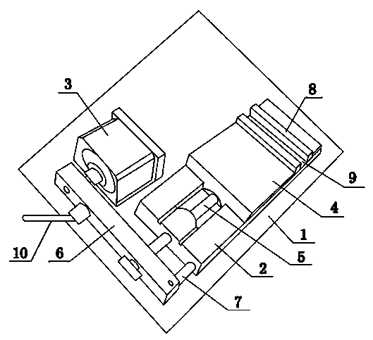
[0017] Pneumatic vise of the present invention comprises base 1, and base 1 is equipped with guide rail 2 and cylinder 3, and guide rail 2 and cylinder 3 are arranged in parallel, and cylinder 3 provides power source, and guide rail 2 guarantees the directivity of clamping; Guide rail 2 is provided with The sliding clamping block 4 and the fixed clamping block 8, between the sliding clamping block 4 and the fixed clamping block 8 is a clamping groove 9, and the workpiece is placed in the clamping groove 9, and the fixed clamping block 8 is arranged at the end of the guide rail 2, which cannot be moved and slides The clamp block 4 is slidably arranged on the guide rail 2; a strut 6 is arranged between the guide rail 2 and the cylinder 3, the output shaft of the cylinder 3 is fixedly connected with one end of the strut 6, and the other end of the strut 6 is connected with a l...


PUM


Abstract

The invention relates to a pneumatic clamping tool. The pneumatic clamping tool is characterized in that a base is provided with a guide rail and an air cylinder in a matched mode, and the guide rail is parallel with the air cylinder; the guide rail is provided with a sliding clamping block and a fixed clamping block, a clamping groove is formed between the sliding clamping block and the fixed clamping block, the fixed clamping block is arranged at the tail end of the guide rail, and the sliding clamping block is arranged on the guide rail in a sliding mode; a supporting rod is arranged between the guide rail and the air cylinder, an output shaft of the air cylinder is fixedly connected with one end of the supporting rod, and the other end of the supporting rod is matched with a limiting shaft arranged on the guide rail in a sliding mode through a hinge pin; the guide rail is provided with a push rod, one end of the push rod is fixedly connected with the supporting rod, and the other end of the push rod penetrates through a guiding hole in the guide rail and is fixedly connected with the sliding clamping block. According to the pneumatic clamping tool, the sliding clamping block is pushed through air pressure to clamp a workpiece, not only can clamping strength be guaranteed, but also operation personnel keep away from turning tools or milling cutters or drill bits, operation safety is guaranteed, and meanwhile control over machining precision of the workpiece is facilitated.

Description

technical field [0001] The invention relates to a pneumatic clamping tool. Background technique [0002] When the workpiece is processed, it is necessary to clamp the workpiece before it can be operated. The clamping tooling on most machine tools is manually operated, and the workpiece is fixed by manual tightening or loosening. This operation method has a certain degree of safety. Hidden dangers, the clamping force of the workpiece is not easy to control, and the workpiece is surrounded by turning tools, milling cutters or drill bits, which will also bring certain dangers to the workers' operation. Contents of the invention [0003] In view of the problems existing in the prior art, the purpose of the present invention is to provide a technical solution for pneumatic clamping tooling. [0004] The pneumatic clamping tool includes a base, which is characterized in that a guide rail and a cylinder are arranged on the base, and the guide rail and the cylinder are arranged i...

Claims


Application Information

Patent Timeline
Patent Type & Authority Applications(China)
IPC IPC(8): B23Q3/00
CPCB23Q3/08
Inventor 刘永强
Owner 新昌县永强空调配件有限公司
Learn More