Fan control system, system management device and fans

A fan controller and fan control technology, applied in the field of fan control system, system manager and fan, to achieve the effect of strong practicability and meet the heat dissipation requirements

Active Publication Date: 2014-03-19
HUAWEI TECH CO LTD
View PDF8 Cites 9 Cited by
  • Summary
  • Abstract
  • Description
  • Claims
  • Application Information

AI Technical Summary

Problems solved by technology

[0004] The purpose of the present invention is to provide a fan control system to solve the problem that the existing fan used for heat dissipation of communication equipment is only suitable for the matching communication equipment

Method used


Image

  • Fan control system, system management device and fans
  • Fan control system, system management device and fans
  • Fan control system, system management device and fans

Examples


Embodiment 1

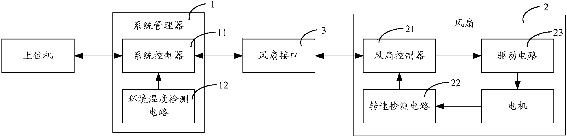
[0038] A fan control system provided in this embodiment, figure 1 The system architecture of the fan control system is shown, and for ease of description, only parts related to the embodiment of the present invention are shown.

[0039] A fan control system, comprising a system manager 1, including one or more fan interfaces, and including one or more fans 2, the system manager 1 is connected to one fan 2 through a fan interface 3, the The fan 2 includes a drive circuit 23 for driving the motor,

[0040] The system manager 1 includes:

[0041]The system controller 11 is configured to first send a specification selection command to the fan controller 21 included in the fan 2 through the fan interface 3, and then send a speed regulation command to the fan controller 21 through the fan interface 3;

[0042] Described fan 2 comprises:

[0043] The fan controller 21 is connected to the driving circuit 23, and is used to first receive the specification selection command through t...

Embodiment 2

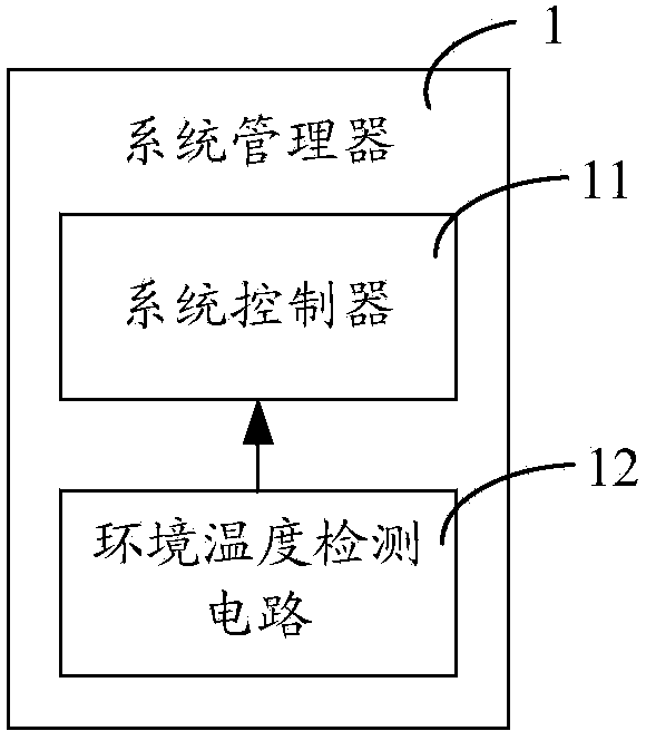
[0064] The system manager 1 provided in this embodiment is applicable to the fan control system provided in Embodiment 1, figure 2 A composition structure of the system manager 1 is shown, and for convenience of description, only parts related to the embodiment of the present invention are shown.

[0065] A system manager 1, the system manager 1 is connected to one or more fans 2, wherein the system manager 1 is connected to one fan 2 through a fan interface 3, and the fan 2 includes a driving motor The drive circuit 23, the system manager 1 includes:

[0066]The system controller 11 is configured to first send a specification selection command to the fan controller 21 included in the fan 2 through the fan interface 3, so that the fan controller 21 selects a fan specification according to the specification selection command and selects the fan specification according to the selected The fan specification controls the driving circuit 23, and then sends a speed regulation comm...

Embodiment 3

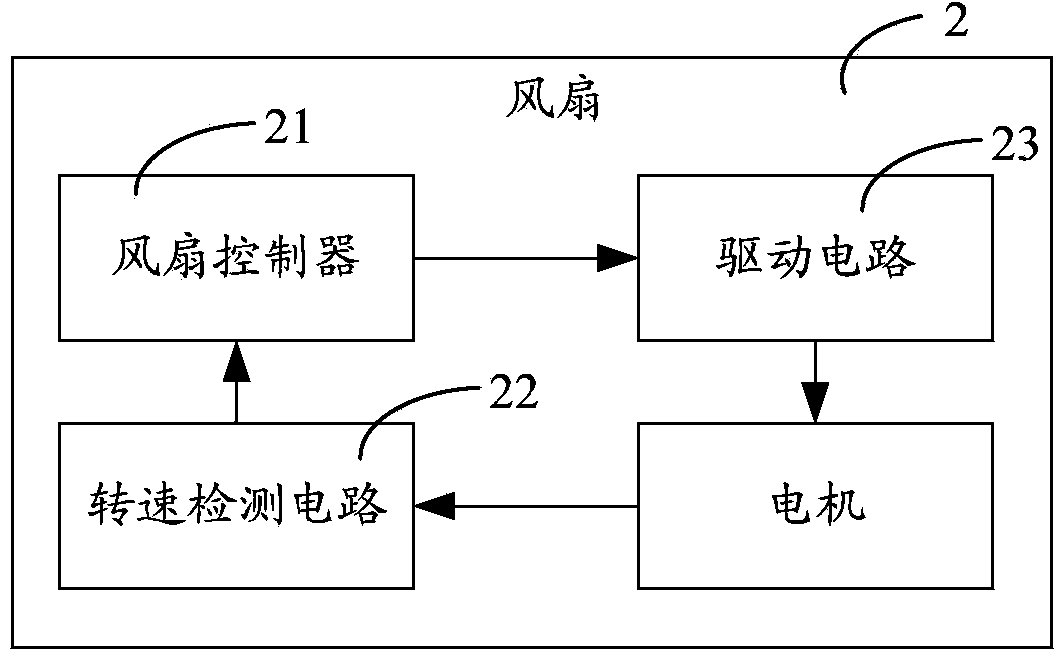
[0078] The fan 2 provided in this embodiment is suitable for the fan control system provided in the first embodiment, image 3 A composition structure of the fan 2 is shown, and for convenience of description, only parts related to the embodiment of the present invention are shown.

[0079] A fan 2, the fan 2 is connected to the system manager 1 through a fan interface 3, the fan 2 includes a driving circuit 23 for driving a motor, and the fan 2 further includes:

[0080] The fan controller 21 is connected to the driving circuit 23, and is used to firstly receive a specification selection command sent by the system controller 11 through the fan interface 3, select a fan specification according to the specification selection command, and select a fan specification according to the selected specification selection command. The fan specification controls the driving circuit 23, and then receives the speed regulation command sent by the system controller 11 through the fan interfa...


PUM


Abstract

The invention applies to the field of communication devices, and discloses a fan control system, a system management device and fans. The fan control system comprises the system management device, one or more fan interfaces and one or more fans, wherein the system management device is connected with one fan through one fan interface and comprises a system controller; each fan comprises a drive circuit, which is used for driving a motor, and a fan controller. Therefore, the system controller can send a specification selection command to the fan controller according to the heat dissipation requirements of different communication devices so as to switch to a matched fan specification; under the fan specification, the system controller sends a speed regulation command to the fan controller to further control the fan rotating speeds, so as to realize accurate control. According to the invention, the heat dissipation requirements of different communication devices are effectively satisfied; the fan rotating speed can be further regulated according to work environments at different temperatures; the practicability is high; humanization is achieved.

Description

technical field [0001] The invention belongs to the field of communication equipment, and in particular relates to a fan control system, a system manager and a fan. Background technique [0002] Communication networks have penetrated into daily life and work, and have become an indispensable existence. The communication network is mainly composed of communication equipment such as mobile communication equipment and Internet communication equipment, so as to realize data transmission between communication equipment and realize business functions such as telephone and web browsing. [0003] With the increase of communication traffic, the load of communication equipment increases, and it is often necessary to use fans to dissipate heat inside the communication equipment. Due to the different power consumption of different communication devices, the amount of heat required to be dissipated is also different, so the fan specifications selected are also different; thus, matching ...

Claims


Application Information

Patent Timeline
Patent Type & Authority Applications(China)
IPC IPC(8): F04D27/00F04D25/08
Inventor 晁汐段伟峰廖义荣
Owner HUAWEI TECH CO LTD
Why Eureka
Try Eureka