Liquid anti-rolling positioning charging and circulating device for liquefied natural gas storage tank

A technology of liquefied natural gas and circulation device, which is applied in gas/liquid distribution and storage, gas processing application, installation device of container structure, etc., which can solve the increase of cost, the threat of storage tank safety, and the inability to specifically control the discharge level, etc. problem, to achieve the effect of preventing stratification and reducing the probability of tumbling

Active Publication Date: 2014-03-19
CHINA NAT OFFSHORE OIL CORP +2
View PDF7 Cites 4 Cited by
  • Summary
  • Abstract
  • Description
  • Claims
  • Application Information

AI Technical Summary

Problems solved by technology

Due to the different LNG densities of different origins and different batches, after a period of time after filling new LNG with different densities and temperatures, the LNG will be stratified in the storage tank. Rollover occurs, which poses a great threat to the safety of the storage tank and also increases the cost of dealing with the BOG (boil-off gas) generated by the rollover
[0003] The patent No. WO 2009 / 011497 discloses unloading at the top and bottom of the storage tank, and cannot specifically control the unloading liquid level
"Natural Gas Industry", Volume 28, Issue 5, the circulation device in Figure 4 in "LNG Overturning Mechanism and Preventive Measures in Large Tanks" published by Wang Liangjun and Liu Yang is an independent circulation device, not integrated with the unloading device

Method used


Image

  • Liquid anti-rolling positioning charging and circulating device for liquefied natural gas storage tank
  • Liquid anti-rolling positioning charging and circulating device for liquefied natural gas storage tank
  • Liquid anti-rolling positioning charging and circulating device for liquefied natural gas storage tank

Examples


Embodiment Construction

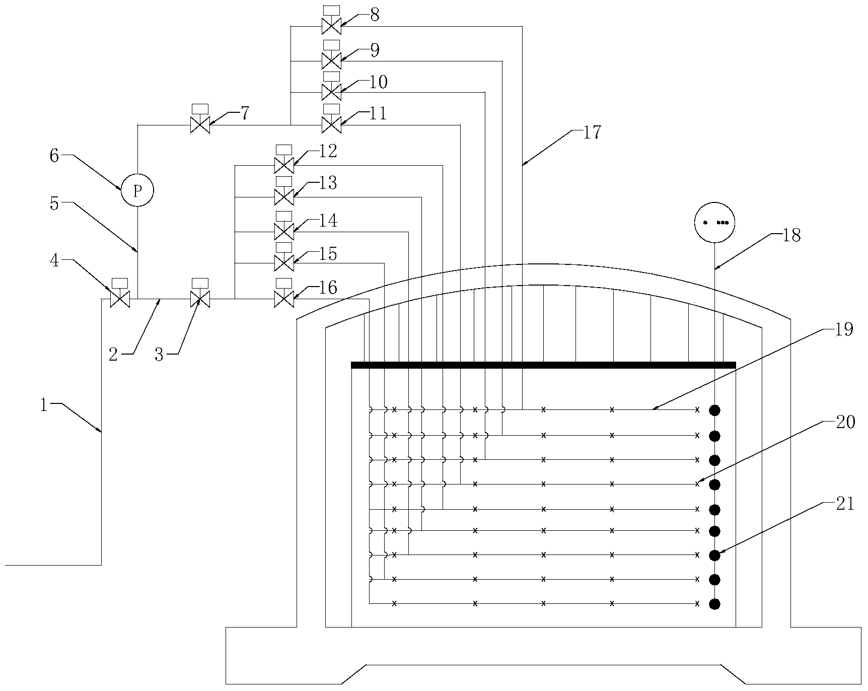
[0010] like figure 2 The liquid anti-rollover positioning filling and circulation device of the liquefied natural gas storage tank shown in the present invention includes a main unloading pipe 1, a heavy sub-unloading pipe 5 connected with the main unloading pipe 1, and a light weight unloading pipe. The sub-discharge pipe 2 is equipped with a main control switch valve 4 on the main discharge pipe 1, and the heavy and light sub-discharge pipes 5 and 2 are respectively installed with The switch control valves 7 and 3 of the light branch pipe, the outlet end of the heavy material branch pipe 5 are connected with the inlets of a plurality of heavy material branch pipes 17, the outlet end of the light branch pipe 2 is connected with the ports of a plurality of light material branch pipes. The inlet is connected, and multi-branch switching control valves 8, 9, 10, 11, 12, 13, 14, 15, 16 are installed on each heavy and light material branch pipe, from bottom to top in the LNG stora...


PUM


Abstract

The invention discloses a liquid anti-rolling positioning charging and circulating device for a liquefied natural gas storage tank. The device comprises a main discharge pipe, and a heavy component discharge branch pipe and a light component discharge branch pipe which are communicated with the main discharge pipe, wherein a master control switching valve is arranged on the main discharge pipe; heavy component branch pipe switching control valves and light component branch pipe switching control valves are respectively arranged on the heavy component discharge branch pipe and the light component discharge branch pipe; the outlet end of the heavy component discharge branch pipe is communicated with inlets of heavy component branch pipes; the outlet end of the light component discharge branch pipe is communicated with inlets of light component branch pipes; multi-branch switching control valves are arranged on each heavy component branch pipe and each light component branch pipe; jet rings are arranged in the liquefied natural gas storage tank at intervals; multiple nozzles are arranged on each jet ring; the outlet end of the heavy component branch pipe is correspondingly communicated with the multiple jet rings arranged on the upper part one by one; the outlet end of the light component branch pipe is correspondingly communicated with the multiple jet rings arranged on the lower part one by one. According to the device, the rolling probability is greatly reduced.

Description

technical field [0001] The invention relates to a liquefied natural gas storage tank, in particular to a liquid anti-rollover positioning filling and circulation device for a liquefied natural gas storage tank. Background technique [0002] Liquefied natural gas is referred to as LNG. With the rapid growth of my country's imported LNG, the storage tanks of LNG receiving stations play an important role as facilities for unloading, storing and exporting LNG. Receiving terminals are usually designed for continuous production operations, and once in operation, it is impossible to empty the LNG storage tanks to store LNG. Existing discharge flushing pipes are single or double entry (such as figure 1 ), the double-entry discharge pipe form consists of main discharge pipe 1-1, heavy (higher density LNG liquid discharge pipe) sub-discharge pipe 4-1, light (lower density LNG liquid discharge pipe ) 5-1, and branch pipe switch control valves 2-1, 3-1. Due to the different LNG densi...

Claims


Application Information

Patent Timeline
IPC IPC(8): F17C13/00F17C13/04
CPCF17C13/004F17C13/02F17C13/021F17C13/026F17C2201/0104F17C2201/032F17C2201/052F17C2205/0326F17C2221/033F17C2223/0161F17C2223/033F17C2223/041F17C2223/047F17C2225/047F17C2250/032F17C2250/0408F17C2250/0439F17C2250/0491F17C2260/042F17C2270/0136
Inventor 杨云杨公升章青李兵闫景鹏吴楠片成荣
Owner CHINA NAT OFFSHORE OIL CORP
Why Eureka
Try Eureka