
Friction-stir-welding temperature field measurement special-purpose backing plate with grooves at bottom and method thereof

A technology of friction stir welding and temperature field, which is applied in the fields of mechanical technology and material engineering, can solve the problems of inability to measure the temperature field of weldments conveniently, accurately and reliably, and achieve the effects of simple structure, guaranteed welding quality and convenient production

Inactive Publication Date: 2014-03-19
JIANGSU UNIV OF SCI & TECH
View PDF3 Cites 6 Cited by
  • Summary
  • Abstract
  • Description
  • Claims
  • Application Information

AI Technical Summary

Problems solved by technology

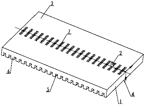
[0008] Purpose of the invention: In order to overcome the deficiencies in the prior art, the present invention provides a special backing plate for measuring the temperature field of friction stir welding with grooves on the bottom and its method, so as to solve the problem that the weldment cannot be measured conveniently, accurately and reliably in the stirring tool. The problem of the temperature field within the range of the shoulder, so as to effectively obtain comprehensive information on the welding temperature field

Method used


Image

  • Friction-stir-welding temperature field measurement special-purpose backing plate with grooves at bottom and method thereof
  • Friction-stir-welding temperature field measurement special-purpose backing plate with grooves at bottom and method thereof
  • Friction-stir-welding temperature field measurement special-purpose backing plate with grooves at bottom and method thereof

Examples


Embodiment Construction

[0032] The present invention will be further described below in conjunction with the accompanying drawings.

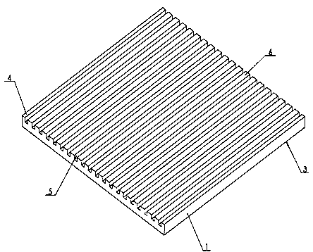
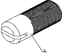
[0033] Such as Figure 1 to Figure 3 As shown, a special backing plate for measuring the temperature field of friction stir welding with grooved bottom of the present invention includes a backing plate main body 1 and set screws 2, the backing plate main body 1 includes an upper bottom surface 3 and a lower bottom surface 4, and the backing plate main body 1 The length direction of the friction stir welding is consistent with the welding direction of the friction stir welding. The lower bottom surface 4 is perpendicular to the welding direction of the friction stir welding. There are several grooves 5 and bosses 6. There are several through-holes 7 in the middle of the backing plate body 1, and a group of through-holes 7 on the center line along the length direction (welding direction) of the main body of the backing plate are tapped with threads, and the set screws 2 ar...


PUM


Abstract

The invention discloses a friction-stir-welding temperature field measurement special-purpose backing plate with grooves at the bottom and a method thereof. The special-purpose backing plate includes a backing-plate main body and set screws. The backing-plate main body includes an upper bottom face and a lower bottom face. The length direction of the backing-plate main body is identical with the welding direction of the friction stir welding. A plurality of grooves and bosses are arranged in the lower bottom face in a direction vertical to the welding direction of the friction stir welding. The grooves and the bosses are arranged alternatively. The middle position of each groove is provided with a through hole. Threads are arranged in a group of through holes on a center line in the length direction of the backing plate. The set screws are screwed into the through holes which are provided with the threads. The special-purpose backing plate and the measurement method thereof are capable of measuring welding thermal-cycle curves of different test points in a three-dimension direction within a shaft shoulder range of a welding piece precisely and reliably in a friction-stir-welding process so that the welding temperature field is understood and grasped comprehensively. Therefore, the special-purpose backing plate and the measurement method are of great significance both to comprehensive and systematical realizing of testing of the friction-stir-welding temperature field and promotion of scientific researches and engineering application of the friction stir welding.

Description

technical field [0001] The invention relates to a bottom grooved friction stir welding temperature field measurement special backing plate and a method thereof, which belong to the field of mechanical technology and material engineering. Background technique [0002] Friction Stir Welding (FSW), as an advanced solid-phase joining technology, has been widely used in aerospace, rail transit, shipbuilding, defense industry and other fields. Usually, the friction stir welding equipment will generate a large friction force and upsetting force during the friction stir welding process, so the weldment must be strictly clamped (including rigid support for the welded back) to ensure the quality of the welded joint . At the same time, friction stir welding is realized through the complex "thermal-mechanical coupling". The welding temperature field is the most closely related parameter to the "thermal-mechanical coupling". It has an important influence, and it is also the bas...

Claims


Application Information

Patent Timeline
Patent Type & Authority Applications(China)
IPC IPC(8): G01K1/14B25B11/00
Inventor 芦笙杨代立陈书锦陈静
Owner JIANGSU UNIV OF SCI & TECH
Learn More