Method and device for deicing direct current transmission line of extra-high-voltage direct current project

A DC transmission line, ultra-high voltage DC technology, applied in the direction of emergency protection circuit devices, cable installation, overhead installation, etc., can solve the problem of implementation, the DC line current cannot meet the ice melting requirements, and the ice melting power cannot be transported, etc. problem, to achieve the effect of preventing serious impact

Active Publication Date: 2014-03-19
STATE GRID CORP OF CHINA +2
View PDF5 Cites 4 Cited by
  • Summary
  • Abstract
  • Description
  • Claims
  • Application Information

AI Technical Summary

Problems solved by technology

This method can generate enough current to melt the ice on the DC line, but it needs to exchange a large amount of power with the AC system at both ends, which is difficult to implement in the dry season
[0005] From the above two methods, it can be obtained that the current method for melting ice of UHV bipolar direct current transmission lines has the problem that the current flowing through the DC line cannot meet the requirements of ice melting, and the electric power required for ice melting cannot be delivered.

Method used


Image

  • Method and device for deicing direct current transmission line of extra-high-voltage direct current project
  • Method and device for deicing direct current transmission line of extra-high-voltage direct current project
  • Method and device for deicing direct current transmission line of extra-high-voltage direct current project

Examples


Embodiment Construction

[0018] The present invention will be described in detail below in conjunction with the accompanying drawings and embodiments.

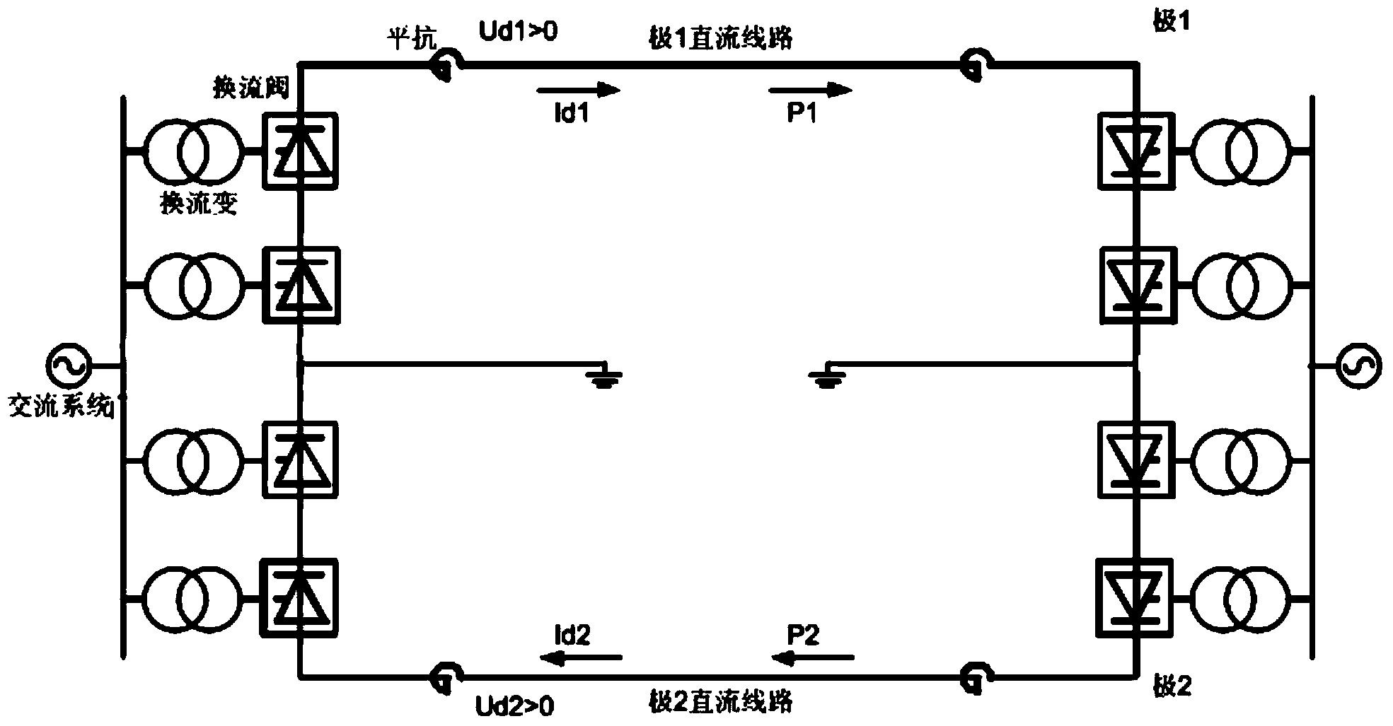
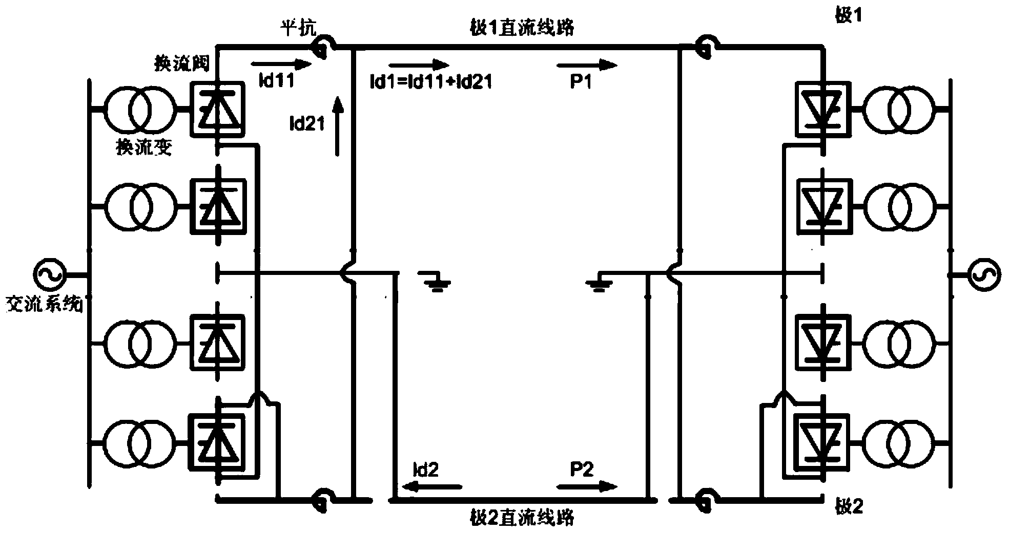
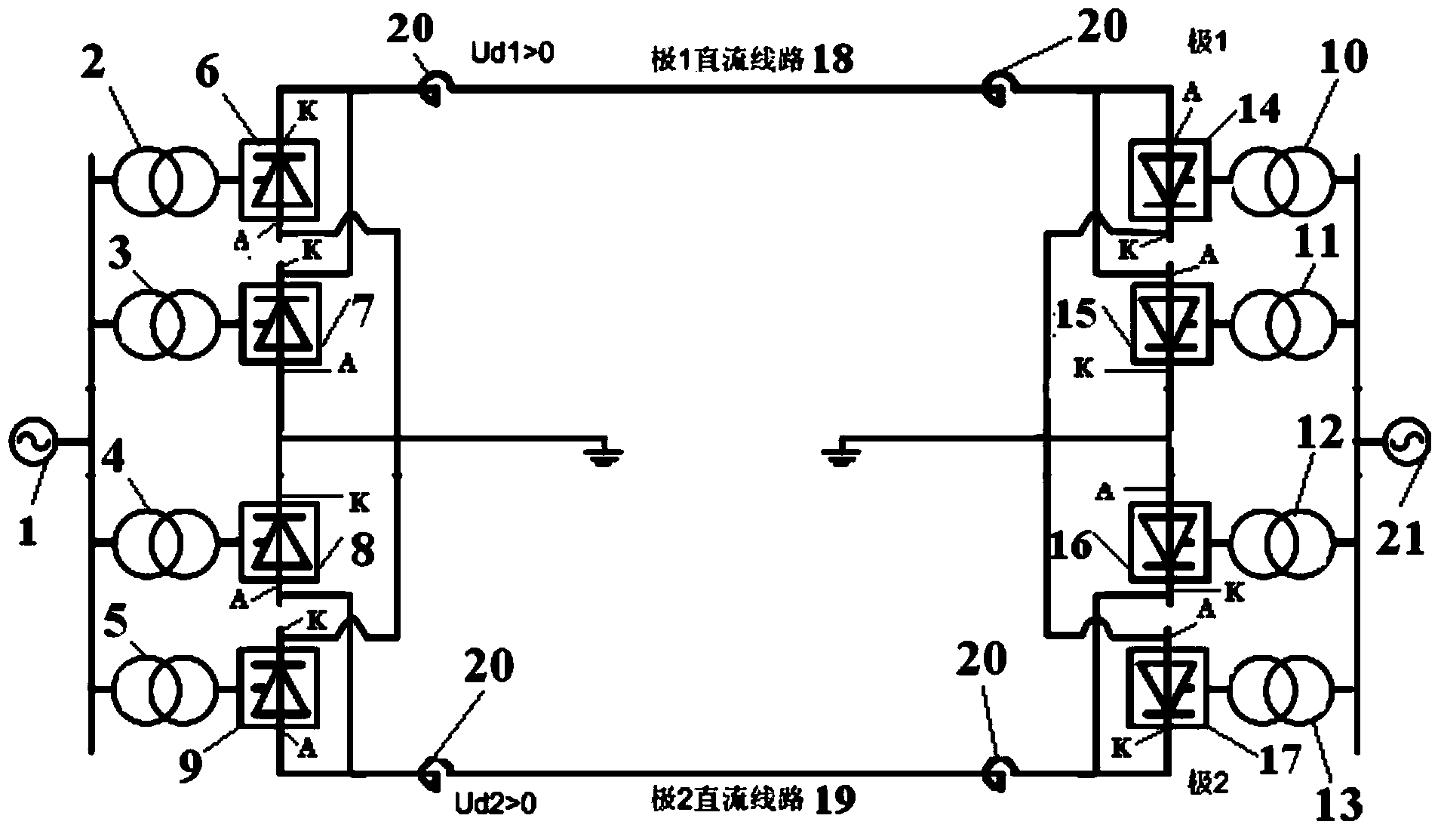
[0019] Such as image 3 , Figure 4 As shown, the present invention provides a deicing device for UHV DC engineering DC transmission lines, which includes a transmitting end AC system 1, a first converter transformer 2, a second converter transformer 3, a third converter transformer 4, a Four converter transformers 5, first converter valve 6, second converter valve 7, third converter valve 8, fourth converter valve 9, fifth converter transformer 10, sixth converter transformer 11, seventh Converter transformer 12, eighth converter transformer 13, fifth converter valve 14, sixth converter valve 15, seventh converter valve 16, eighth converter valve 17, pole 1 DC transmission line 18, pole 2 DC Transmission line 19, smoothing reactor 20 and AC system 21 at the receiving end. Wherein, when the voltage Ud1 at both ends of pole 1 DC transmission line 18...


PUM


Abstract

The invention relates to a method and a device for deicing a direct current transmission line of an extra-high-voltage direct current project. A transmitting end alternating current system is connected with alternating current sides of a first converter transformer to a fourth converter transformer, direct current sides of the first converter transformer to the fourth converter transformer are connected with a first converter valve to a fourth converter valve, direct current sides of a fifth converter transformer to an eighth converter transformer are connected with a fifth converter valve to an eighth converter valve, alternating current sides of the fifth converter transformer to the eighth converter transformer are connected with a receiving end alternating current system, cathodes of the first converter valve and a first converter valve are parallelly connected with one end of a pole-1 direct current line, the other end of the pole-1 direct current line is connected with anodes of the fifth converter valve and a sixth converter valve, the anode of the first converter valve and the anode of the second converter valve are in common ground connection, the cathode of a third converter valve and the cathode of the fourth converter valve are in common ground connection, the anode of the fourth converter valve and the cathode of the third converter valve are parallelly connected to one end of a pole-2 direct current line, the other end of the pole-2 direct current line is connected with the cathodes of the eighth converter valve and a seventh converter valve, the cathode of the fifth converter valve and the cathode of the sixth converter valve are in common ground connection, the anode of the seventh converter valve and the anode of the eighth converter valve are in common ground connection, and two ends of the pole-1 direct current line and two ends of the pole-2 direct current line are connected with smoothing reactors.

Description

technical field [0001] The invention relates to a method and device for melting ice of direct current transmission lines, in particular to a method and device for melting ice of direct current transmission lines of UHV direct current projects. Background technique [0002] At present, accidents of high-voltage transmission line disconnection, tower collapse, and tower collapse due to icing and snow accumulation on transmission lines occur from time to time. The accidents of high-voltage transmission line disconnection and tower collapse have seriously affected the safe operation of the power grid, resulting in large-scale power outages ACCIDENT. In order to prevent the occurrence of such accidents, the ice and snow on the wires must be melted in time. The ice-melting methods of the DC lines of the bipolar long-distance DC transmission system used in the existing ±800 kV and above DC UHV DC projects can be divided into the following two categories: [0003] One is not to ch...

Claims


Application Information

Patent Timeline
Patent Type & Authority Applications(China)
IPC IPC(8): H02G7/16H02H7/26
Inventor 尹健马玉龙陈东张进宋胜利卢亚军蒲莹樊纪超张云晓
Owner STATE GRID CORP OF CHINA
Why Eureka
Try Eureka