Permanent magnet transmission mechanism

A technology of permanent magnet transmission and permanent disk, which is applied in the direction of electromechanical transmission devices, electromechanical devices, electric components, etc., can solve the problems of magnetic steel magnetic reduction, unfavorable equipment heat dissipation, and potential safety hazards, so as to avoid magnetic steel magnetic deterioration and avoid Debris fly out to hurt people and prolong the service life

Inactive Publication Date: 2014-03-19
山东东朋自控仪表有限公司
View PDF8 Cites 3 Cited by
  • Summary
  • Abstract
  • Description
  • Claims
  • Application Information

AI Technical Summary

Problems solved by technology

In order to ensure energy transmission efficiency, the gap between the permanent magnet rotor and the conductor rotor is generally small, but if the permanent magnet rotor and the conductor rotor are displaced due to load or motor shaft shifting, friction may be formed and debris may fly out. In the first form, there will be safety hazards, and on the other hand, external debris will easily enter the gap and cause wear and tear.
For the second form, ...

Method used


Image

  • Permanent magnet transmission mechanism
  • Permanent magnet transmission mechanism
  • Permanent magnet transmission mechanism

Examples


Embodiment Construction

[0017] The principles and features of the present invention are described below in conjunction with the accompanying drawings, and the examples given are only used to explain the present invention, and are not intended to limit the scope of the present invention.

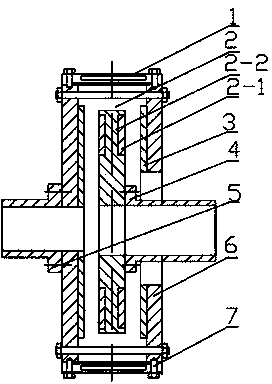
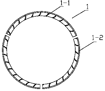
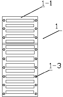
[0018] Such as Figure 1 to Figure 3 As shown, a permanent magnet transmission mechanism includes a conductor rotor and a permanent magnet rotor, the conductor rotor includes a pair of rotor plates fixedly connected by bolts, the permanent magnet rotor 2 is arranged between the pair of rotor plates, The rotor plate includes a base plate 6 and a conductor disk 3 arranged on the base plate, a shield 1 is provided on the periphery of the base plate, and a wind fin 1-1 is arranged on the shield 1, and the shield 1 is at least Comprise two garden arc covers 1-2.

[0019] The permanent magnet rotor 2 includes a permanent magnetic disk 2-2 and magnetic steel blocks 2-1 arranged on both sides of the permanent magnetic disk...


PUM


Abstract

The invention relates to a permanent magnet transmission mechanism which comprises a conductor rotor and a permanent magnet rotor. The conductor rotor comprises a pair of rotor plates which are fixedly connected through bolts, and the permanent magnet rotor is arranged between the rotor plates. The permanent magnet transmission mechanism is characterized in that each rotor plate comprises a substrate and a conductor disk arranged on the substrate, a shield is arranged on the periphery of each substrate, wind wings are arranged on each shield, each shield at least includes two arc-shaped shields, and the permanent magnet rotor comprises a permanent magnet disk and magnetic steel blocks arranged on two surfaces of the permanent magnet disk. The permanent magnet transmission mechanism has the advantages that safety can be ensured, and the permanent magnet transmission mechanism has a fine cooling effect.

Description

technical field [0001] The invention relates to the technical field of permanent magnet transmission, in particular to a permanent magnet transmission mechanism. Background technique [0002] At present, the permanent magnet coupling transmission mechanism has been widely used in industrial sites, such as fans and water pumps using permanent magnet transmission, especially for high-power loads. Due to the high reliability and low failure rate of the permanent magnet transmission mechanism, it can adapt to various harsh environments. In mining equipment, a transmission mechanism with a permanent magnet rotor in the middle and conductor rotors on both sides is mostly used. The conductor rotors on both sides are connected by bolts. Generally, there are two forms around the conductor rotor. One is that the conductor rotor is open around the periphery, and the other is The species is completely enclosed. In order to ensure energy transmission efficiency, the gap between the...

Claims


Application Information

Patent Timeline
IPC IPC(8): H02K51/00H02K5/10H02K5/18
Inventor 李建朋刘锋梁春海
Owner 山东东朋自控仪表有限公司
Why Eureka
Try Eureka