Compact elastic fixed bearing

A fixed support and elastic fixation technology, which is applied to springs, vehicle components, and power plant gas intake, etc., can solve the problem that the fixed support cannot be used

Active Publication Date: 2014-03-19
韦古减震有限公司
View PDF6 Cites 5 Cited by
  • Summary
  • Abstract
  • Description
  • Claims
  • Application Information

AI Technical Summary

Problems solved by technology

The known fixed support as described in EP 0 184 661 A2 cannot be used

Method used


Image

  • Compact elastic fixed bearing
  • Compact elastic fixed bearing
  • Compact elastic fixed bearing

Examples


Embodiment Construction

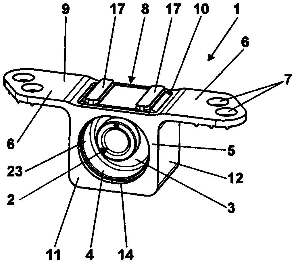
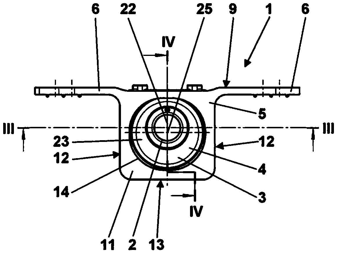
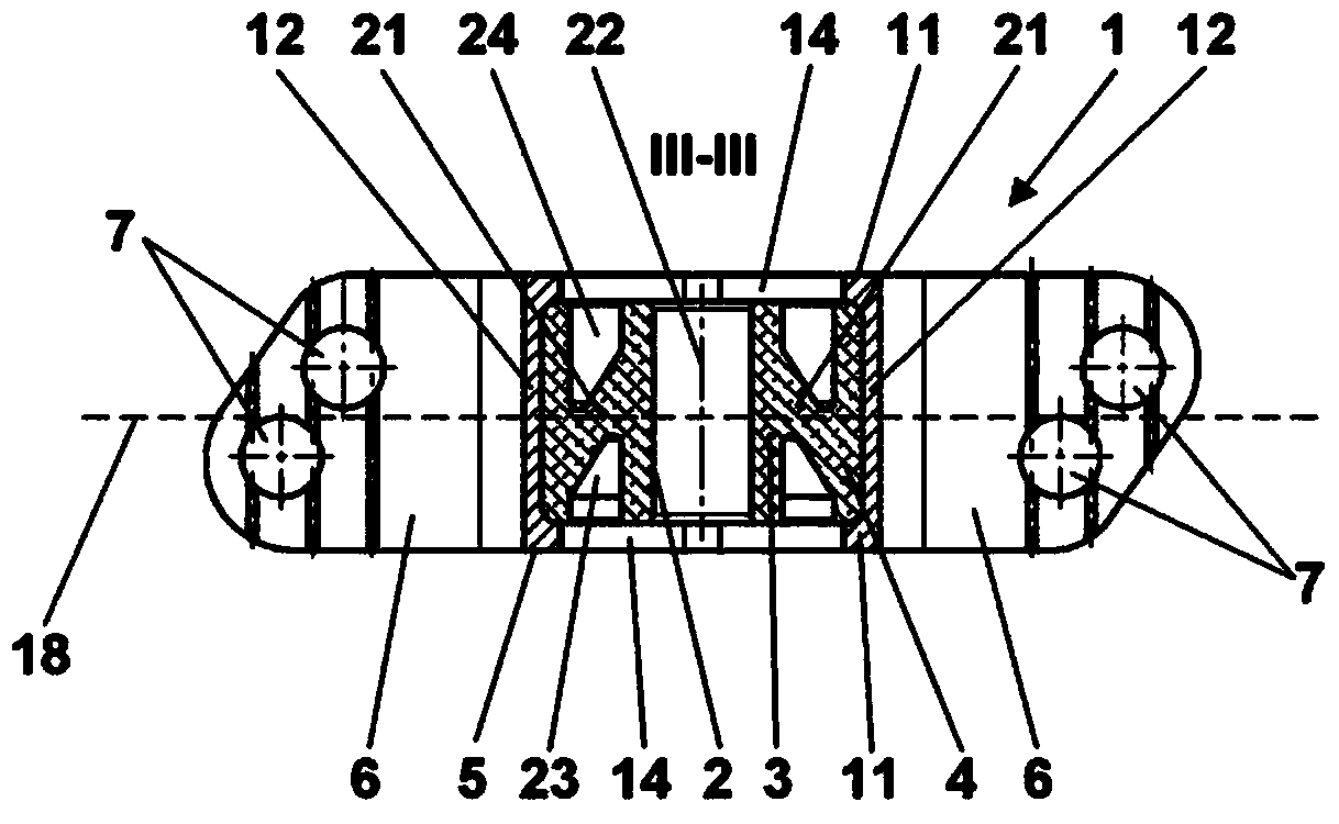
[0046] exist Figure 1 to Figure 4 in various views as a whole and in Figure 5 and Figure 6 The fastening support 1 , shown in its two individual parts, is used for mounting an exhaust system, not shown here, on the underbody of a motor vehicle, likewise not shown here. For the exhaust gas system, the fixed bearing has a bearing bush 2 . The bearing bush is part of the elastic body 3 made of elastomer material 4 . The elastic body 3 is produced separately from the elastomer material 4 and then inserted into a dimensionally stable frame 5 . The dimensionally stable frame 5 has a suspension 6 with fastening bores 7 for rigid fastening to the vehicle floor. In this fastening condition, an opening 8 in the upper side 9 of the rigid frame 5 is closed, through which opening the elastic body 3 is inserted into the frame 5 . The elastic body 3 is arranged in a cavity 10 in the frame 5 , wherein the cavity 10 has a rectangular parallelepipedal basic shape. All walls 11 to 13 deli...


PUM


Abstract

An elastic fixed bearing (1) for mounting a dynamically loaded component to be supported on a supporting component has a dimensionally rigid frame (5), fastening devices (6, 7) for fastening the frame (5) rigidly to the supporting component, and a spring body (3) by means of which a bearing bush (2) for the component to be supported is elastically supported within the frame (5) in a main plane of the fixed bearing (1). The spring body (3), which is produced from an elastomer material (4), is inserted in a form-fitting manner into a cavity (10) of the frame (5), said cavity has a cuboidal basic shape, and those walls (11) of said cavity which run parallel to the main plane of the fixed bearing (1) have central openings (14) with a rounded periphery for the leadthrough of the component to be supported.

Description

technical field [0001] The invention relates to an elastic fixing bearing for supporting a dynamically loaded component to be supported on a supporting component, said fixing bearing having the features of the preamble of independent claim 1 . [0002] In particular, the invention is directed to an elastic fastening support for suspending an exhaust system of a motor vehicle on the underbody of the motor vehicle. [0003] An elastic fastening bearing is understood here to be a bearing which can be fastened rigidly and thus also in a rotationally fixed manner to the supporting component, in particular to the vehicle floor, by means of a dimensionally stable structural element. Background technique [0004] An elastic fastening mount for mounting an exhaust system on the underbody of a motor vehicle is known from EP 0 184 661 A2, said fastening mount having the features of the preamble of independent claim 1 . In this case, the elastic body has an annular inner part serving a...

Claims


Application Information

Patent Timeline
Patent Type & Authority Applications(China)
IPC IPC(8): B60K13/04
CPCB60K13/04F16F1/3835F16F1/3849
Inventor W·格布哈特H·齐默尔曼S·格兰普克
Owner 韦古减震有限公司
Why Eureka
Try Eureka