Sliding component

A sliding part and sliding surface technology, applied in engine components, engine seals, mechanical equipment, etc., can solve the problem of easy lubrication of seal blocking parts, and achieve the effect of ensuring lubricity, reducing sliding torque, and maintaining tightness

Active Publication Date: 2014-03-19
EAGLE INDS
View PDF7 Cites 6 Cited by
  • Summary
  • Abstract
  • Description
  • Claims
  • Application Information

AI Technical Summary

Problems solved by technology

[0005] In the prior art described above, since the grating portion 50 is provided, the lubricity of the sliding surface is improved from the initial stage of ro

Method used


Image

  • Sliding component
  • Sliding component
  • Sliding component

Examples


Embodiment approach 1

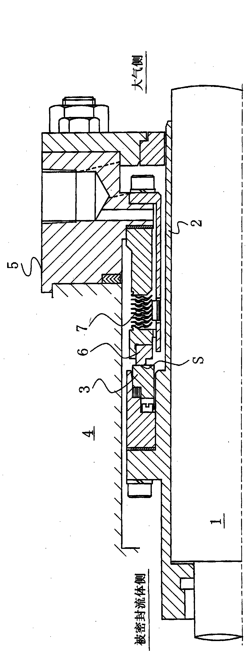
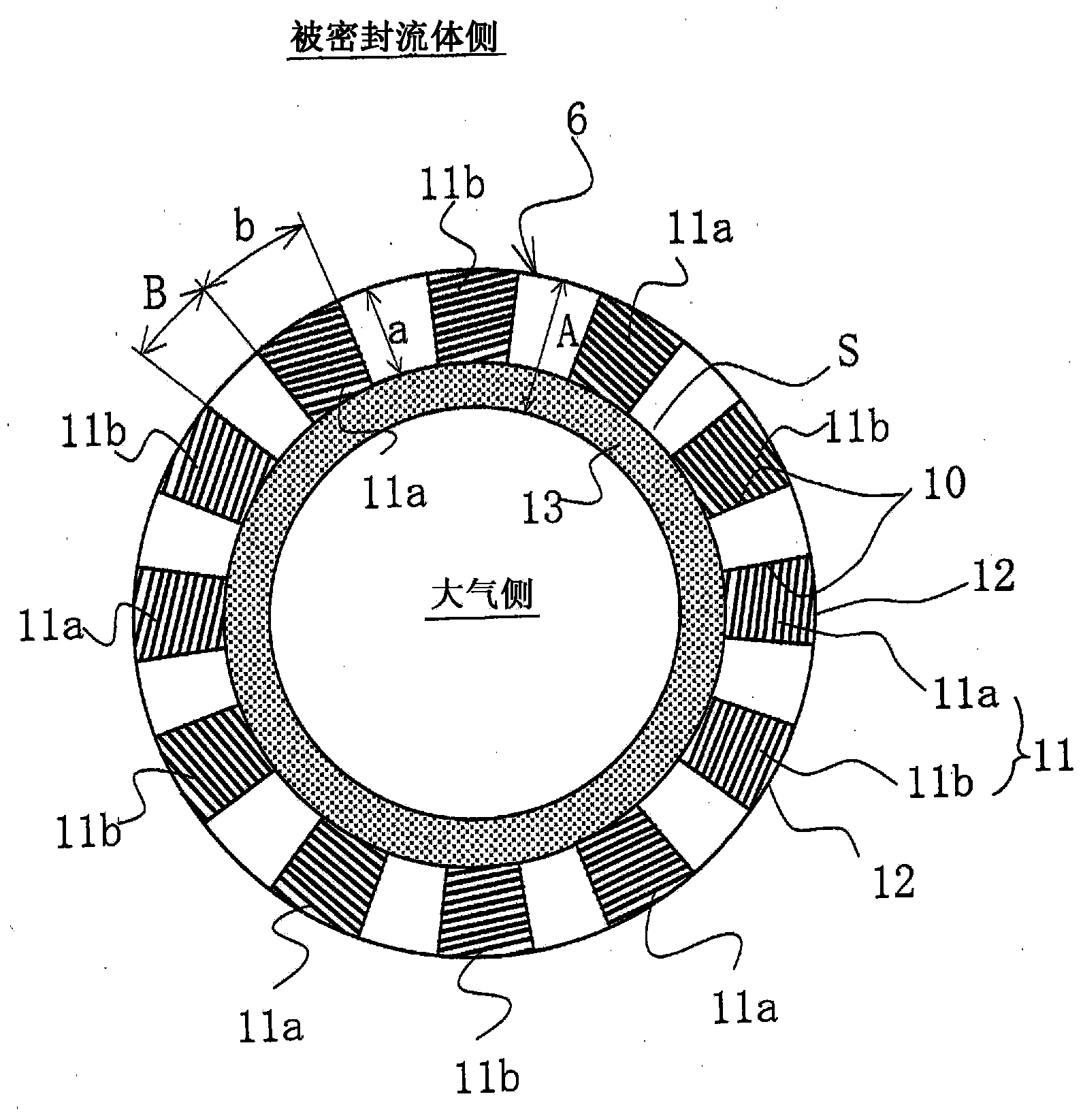
[0044] image 3 is shown in figure 1 and figure 2 Among the sliding surfaces of the stationary ring 6 and the rotating ring 3, the sliding surface S of the stationary ring 6, which has a smaller radial width, is formed with a sealed fluid receiving area, a suction portion, and a seal barrier portion with excellent lubricity. A top view of one embodiment of the case.

[0045] exist image 3 Among them, the fixing ring 6 is called a sealing ring, and is mostly formed of carbon (soft material). A plurality of sealed fluid storage areas 10 separated in the circumferential direction are formed on the sliding surface S of the stationary ring 6. The sealed fluid storage areas 10 are formed on a part of the radial direction of the sliding surface S, and are sealed with the outer peripheral side 12. The fluid storage space is directly connected.

[0046] In addition, in the case of an outer type mechanical seal in which the sealed fluid side exists inside the rotating ring 3 and...

Embodiment approach 2

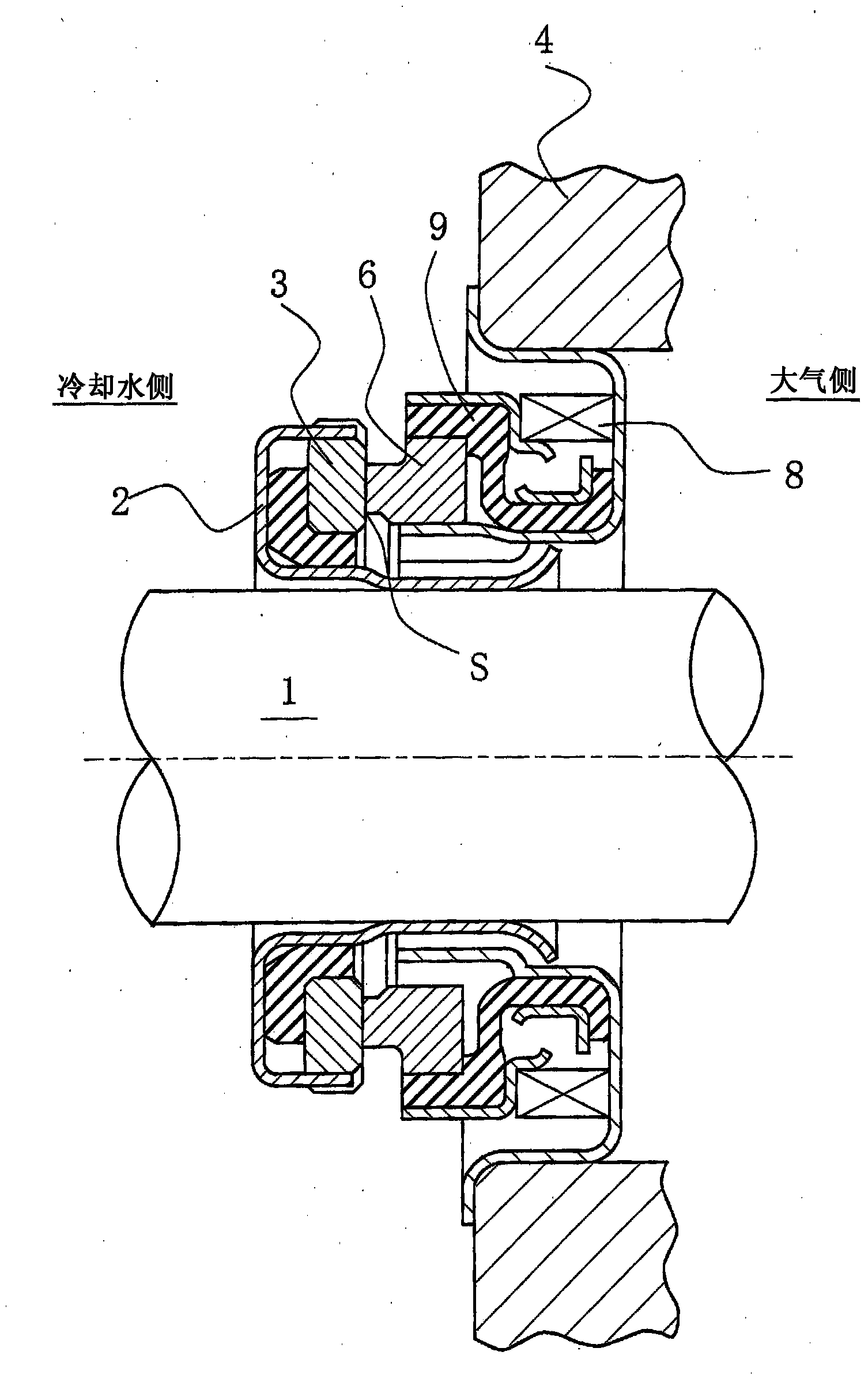
[0083] Image 6 is in figure 1 and 2 Among the mechanical seals of the fixed ring and the rotating ring, one of the cases where the sliding surface of the rotating ring with a large radial width is formed with a sealed fluid receiving area, a suction portion, and a seal stopper portion excellent in lubricity The drawing of the embodiment is a sectional view taken along a plane perpendicular to the sliding surface.

[0084] exist Image 6 Among them, the rotating ring 3 is called an adapter ring, and it is mostly formed of SiC (hard material). On the sliding surface S of the rotary ring 3, a plurality of sealed fluid storage areas 10 separated in the circumferential direction are formed. These plurality of sealed fluid storage areas 10 are formed on a part of the sliding surface S with spaces left outside and inside in the radial direction of the sliding surface S, and a part of the sealed fluid storage area 10 on the sealed fluid side It is formed so as not to be covered...


PUM

PropertyMeasurementUnit
Thicknessaaaaaaaaaa

Abstract

To provide a sliding component that does not leak when standing still, operates as well as prevents leakage by using fluid lubrication during rotation including the initial period of rotation, and can achieve both sealing and lubrication. A sliding component is characterized by: a plurality of housing blocks for fluid to be sealed, separated in the circumferential direction, being formed in either a fixed ring or a sliding surface of a rotating ring so as to communicate with a housing space for fluid to be sealed; a pumping unit that causes a pumping action by relative rotational sliding between the fixed ring and the rotating ring being formed in the floor section of the plurality of housing blocks for fluid to be sealed; the pumping unit formed in the floor section of the plurality of housing blocks for fluid to be sealed comprising a suction pumping unit that operates in the direction that the fluid to be sealed is sucked in and a discharge pumping unit that operates in the direction that the fluid to be sealed is discharged; and a seal dam unit, on the opposite side to the fluid to be sealed side of the sliding surface having the housing blocks for fluid to be sealed formed therein, being formed from a sliding material having excellent lubrication properties.

Description

technical field [0001] The present invention relates to relatively rotating sliding parts, such as sliding parts of mechanical seals used in automobiles, general industrial equipment or other sealing fields. Background technique [0002] As a sealing device to prevent the leakage of the sealed fluid, in a structure composed of two parts, such as a mechanical seal, in order to maintain the sealing performance for a long time, it is necessary to take into account the contradictory conditions of "sealing" and "lubrication". The two members are configured to rotate relative to each other, and the end faces on the plane slide against each other. In particular, in recent years, for the sake of environmental protection and the like, the demand for low friction has been further increased, and mechanical loss has been reduced while preventing leakage of sealed fluid. As a method of reducing friction, it is possible to achieve a so-called fluid lubrication state in which dynamic pres...

Claims


Application Information

Patent Timeline
IPC IPC(8): F16J15/34
CPCF16J15/34F16J15/3412F16J15/3496F16J15/3428F16J15/342
Inventor 细江猛井上秀行
Owner EAGLE INDS
Why Eureka
Try Eureka