Apparatus and methods for biasing power amplifiers

A technology for power amplifiers and current amplifiers, which is applied to power amplifiers, components of amplifying devices, amplifiers, etc., and can solve problems such as out-of-band transmission of wireless devices.

Active Publication Date: 2014-03-19
SKYWORKS SOLUTIONS INC
View PDF3 Cites 11 Cited by
  • Summary
  • Abstract
  • Description
  • Claims
  • Application Information

AI Technical Summary

Problems solved by technology

Managing the amplification of RF signals can be important because amplifying RF signals to incorrect power levels can cause wireless devices to transmit out of band

Method used


Image

  • Apparatus and methods for biasing power amplifiers
  • Apparatus and methods for biasing power amplifiers
  • Apparatus and methods for biasing power amplifiers

Examples


Embodiment Construction

[0033] Headings, if any, are provided here for convenience only and do not necessarily affect the scope or meaning of the claimed invention.

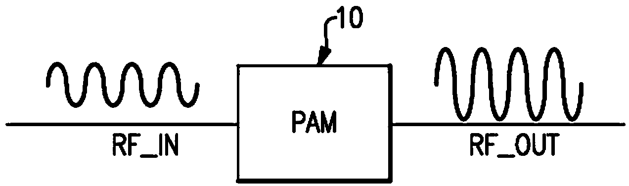
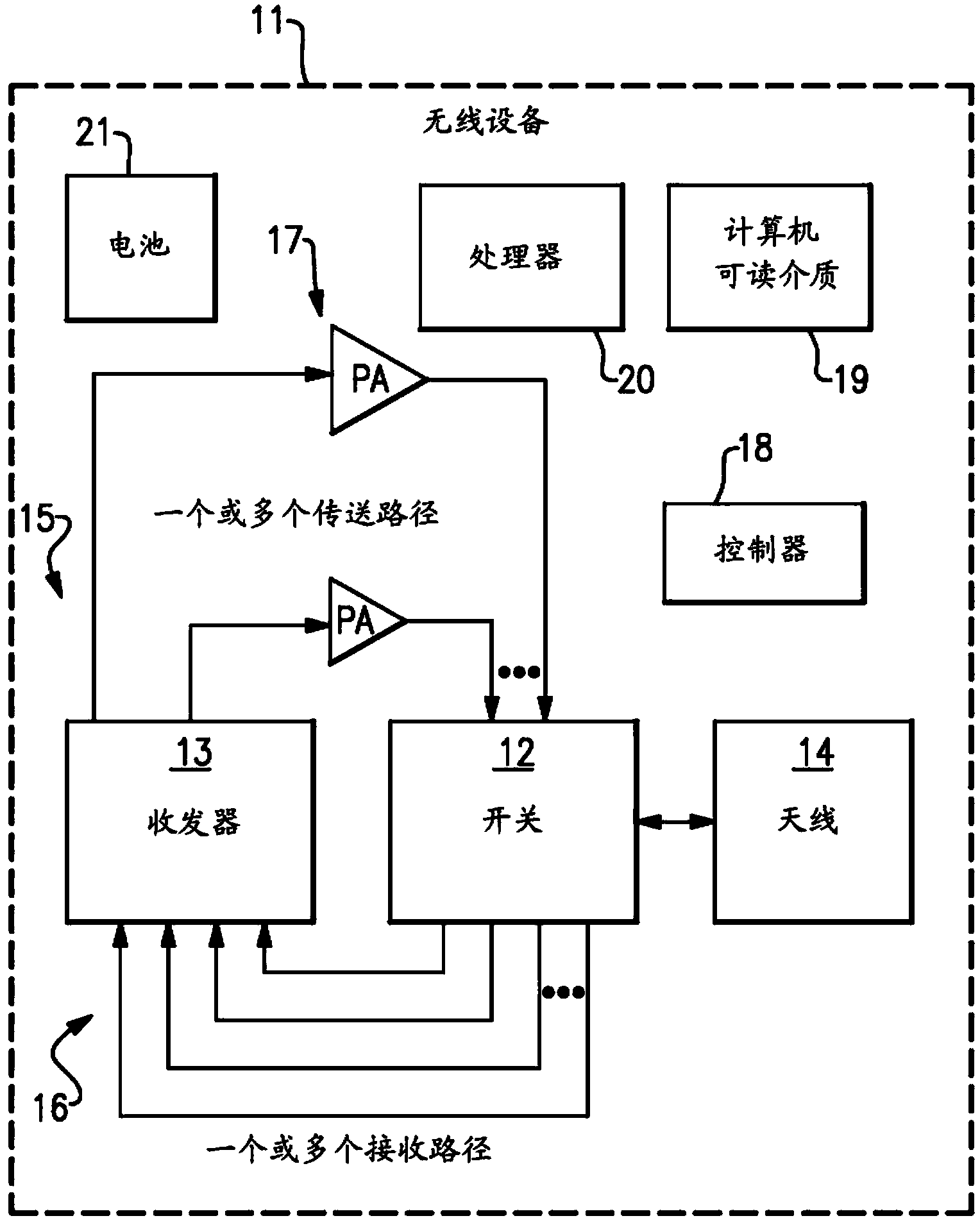
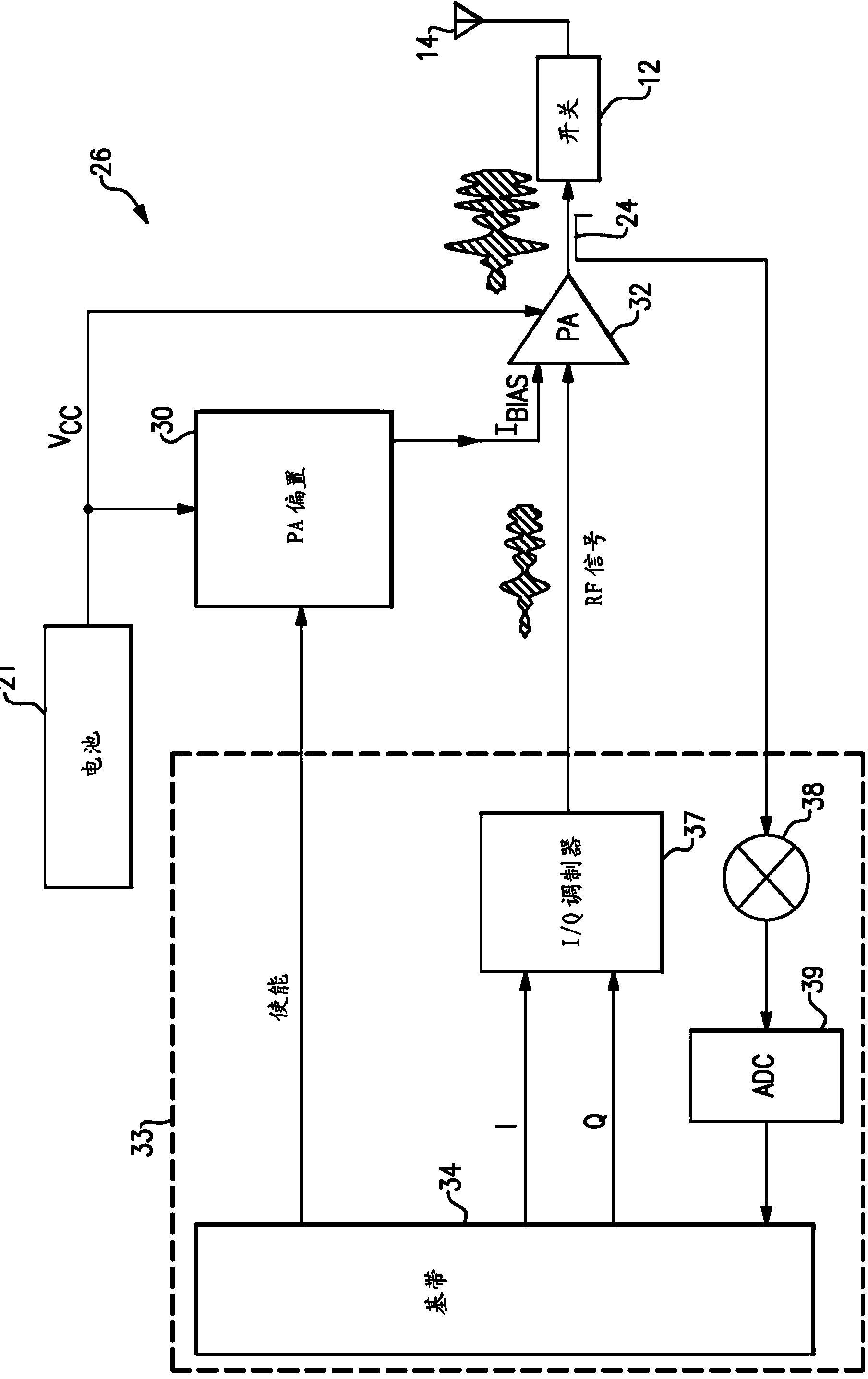
[0034] An apparatus and method for biasing a power amplifier is disclosed herein. In some implementations, a power amplifier and a power amplifier bias block are provided. The power amplifier may be used to amplify radio frequency (RF) signals for transmission, and the power amplifier biasing block may be used to bias the power amplifier. The power amplifier biasing block can receive an enable signal that can be used to enable or disable the power amplifier to pulse the output of the power amplifier.

[0035]In some implementations, a power amplifier bias block includes a main bias circuit and a gain correction block that includes a time-dependent signal generator and a current amplifier. A time-dependent signal generator or control block may be used to shape the enable signal to generate a control current, which may be amplified by a...


PUM


Abstract

Apparatus and methods for biasing a power amplifier are disclosed. In one embodiment, a method of biasing a power amplifier includes shaping an enable signal using a time-dependent signal generator to generate a control current, amplifying the control current using a current amplifier to generate a correction current, and generating a bias current for a power amplifier using a primary biasing circuit. The primary biasing circuit is configured to use the correction current to correct for a variation in gain of the power amplifier when the power amplifier is enabled.

Description

technical field [0001] Embodiments of the present invention relate to an electronic system, and in particular, to a radio frequency (RF) electronic device. Background technique [0002] RF power amplifiers can be used to boost the power of RF signals having relatively low power. Thereafter, the boosted RF signal can be used for various purposes, including driving the transmitter's antenna. [0003] Power amplifiers may be included in mobile phones to amplify RF signals for transmission. For example, in a mobile phone communicating using a wireless local area network (WLAN) protocol and / or any suitable communication standard, a power amplifier may be used to amplify RF signals. Managing the amplification of the RF signal can be important because amplifying the RF signal to an incorrect power level can cause the wireless device to transmit out of band. [0004] A need exists for improved power amplifier systems. Additionally, there is a need for improved power amplifier bi...

Claims


Application Information

Patent Timeline
Patent Type & Authority Applications(China)
IPC IPC(8): H03F1/30H03F3/24
CPCH03F3/24H03F3/21H03G3/007H03F3/19H03G3/3042H03F1/30H03F1/0205H03F3/195H03F3/211H03F3/213H03F2200/129H03F2200/18H03F2200/336H03F2200/387H03F2200/451H04B1/3827
Inventor P.李P.T.迪卡罗
Owner SKYWORKS SOLUTIONS INC
Why Eureka
Try Eureka