Anesthesia pharyngoscope mirror

A technology of laryngoscope lens and lens, which is applied in the field of anesthesia laryngoscope laryngoscope lens, can solve the problems of inconvenient industrial production, reduced service life, and affecting the use effect, and achieve the effects of preventing cross-infection, increasing service life, and reducing maintenance costs

Inactive Publication Date: 2014-03-26
SHANDONG YIHE MEDICAL TECH
View PDF11 Cites 13 Cited by
  • Summary
  • Abstract
  • Description
  • Claims
  • Application Information

AI Technical Summary

Problems solved by technology

[0002] The back end of the bottom of the existing straight or curved anesthesia laryngopharynx laryngoscope is equipped with a supporting part. When in use, the medical staff will lightly touch the supporting part on the lower teeth of the patient, so that the front end of the laryngoscope is placed in the oral cavity, and the To expose the glottis; and any one of devices such as a camera, an oxygen supply tube, a drug delivery tube, or a sputum suction guide tube, or any combination thereof, is provided at the bottom of the laryngoscope at the front end of the support component. Due to the existence of supporting parts, the device is difficult to fix at the bottom of the laryngoscope blade, which is not convenient for industrial production and increases the manufacturing cost; the device is fixedly installed on the laryngoscope blade, and its pipeline is exposed, which is easily damaged by bumps during use, affecting the use effect and increasing maintenance The cost reduces the service life; there are gaps between the devices, and blood and secretions are likely to remain between the gaps after use, which is not easy to clean and disinfect, leading to the breeding of bacteria and easy to cause cross-infection

Method used


Image

  • Anesthesia pharyngoscope mirror
  • Anesthesia pharyngoscope mirror
  • Anesthesia pharyngoscope mirror

Examples


Embodiment 1

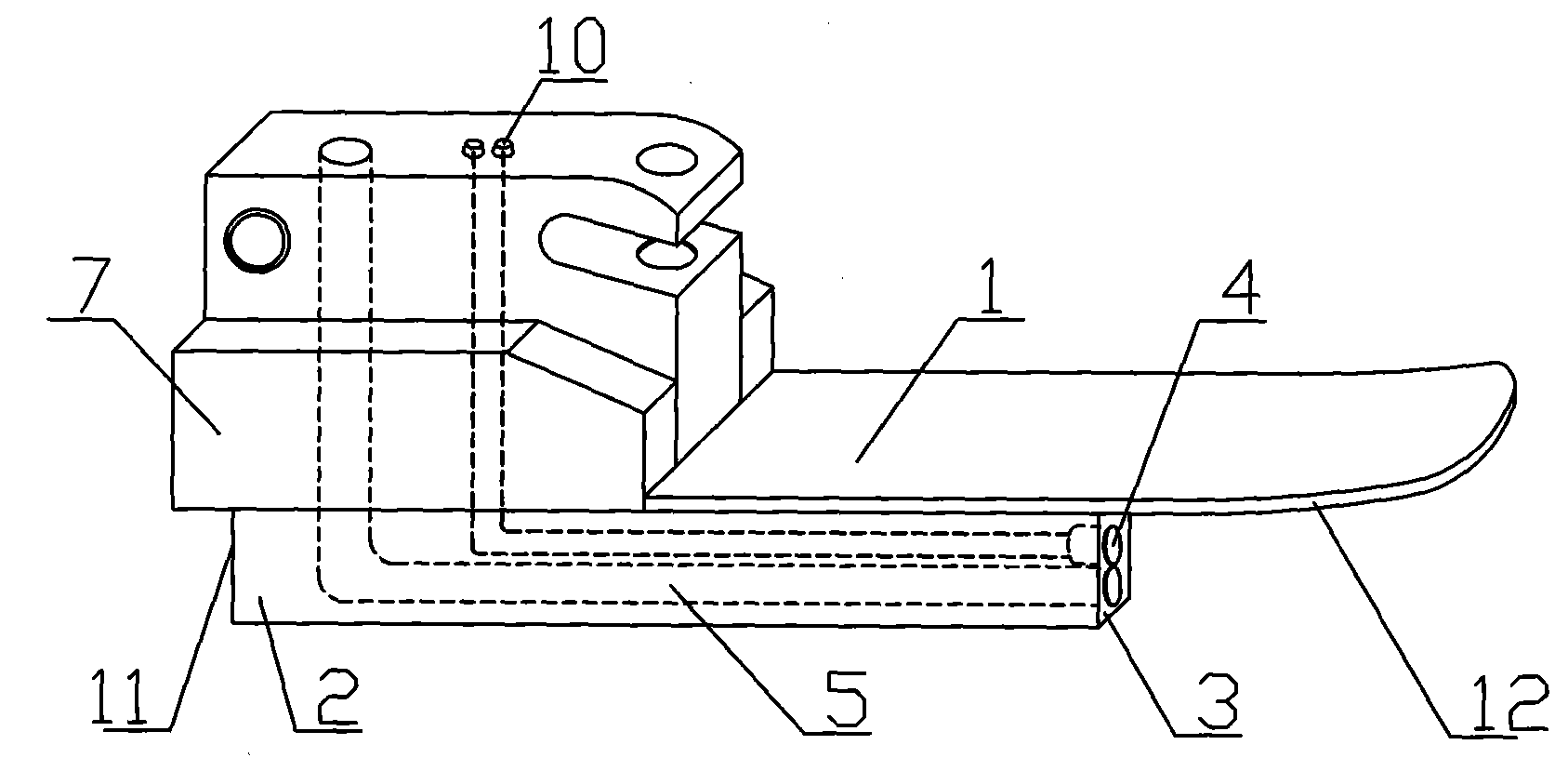
[0037] Example 1: Such as figure 1 As shown, an anesthesia laryngoscope laryngoscope lens includes a laryngeal lens main body 1, which is a straight laryngeal lens, or as figure 2 As shown, the laryngeal lens body 1 is a curved laryngeal lens, or as image 3 As shown, the laryngeal lens body 1 is a hook laryngeal lens; the laryngeal lens body 1 is composed of a lens blade 12 located below and a tailstock 7 installed above the rear end of the lens blade 12 and integrated with the lens blade 12; The bottom surface of the main body 1 lens blade 12 is provided with a support tube 2 with an open end and a hollow end. The open end 3 of the support tube faces the front end of the lens blade 12, and the closed end 11 of the support tube is placed at the rear end of the lens blade 12. The support tube 2 replaces the traditional laryngeal lens. The supporting part, when in use, the medical staff lightly touches the supporting tube 2 on the lower teeth of the patient, so that the front end...

Embodiment 2

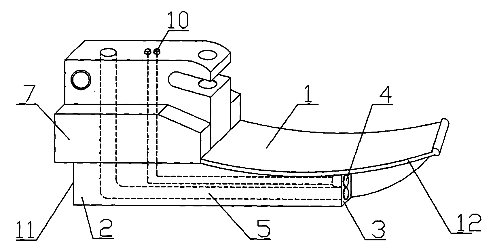
[0038] Example 2: Such as Figure 4 As shown, an anesthesia laryngoscope laryngoscope lens includes a laryngeal lens main body 1, which is a straight laryngeal lens, or as Figure 5 As shown, the laryngeal lens body 1 is a curved laryngeal lens, or as Image 6 As shown, the laryngeal lens body 1 is a hook laryngeal lens; the laryngeal lens body 1 is composed of a lens blade 12 located below and a tailstock 7 installed above the rear end of the lens blade 12 and integrated with the lens blade 12; The bottom surface of the main body 1 lens blade 12 is provided with a support tube 2 with an open end and a hollow end. The open end 3 of the support tube faces the front end of the lens blade 12, and the closed end 11 of the support tube is placed at the rear end of the lens blade 12. The support tube 2 replaces the traditional laryngeal lens. The supporting part, when in use, the medical staff will lightly touch the supporting tube 2 on the patient's lower teeth, so that the front end ...

Embodiment 3

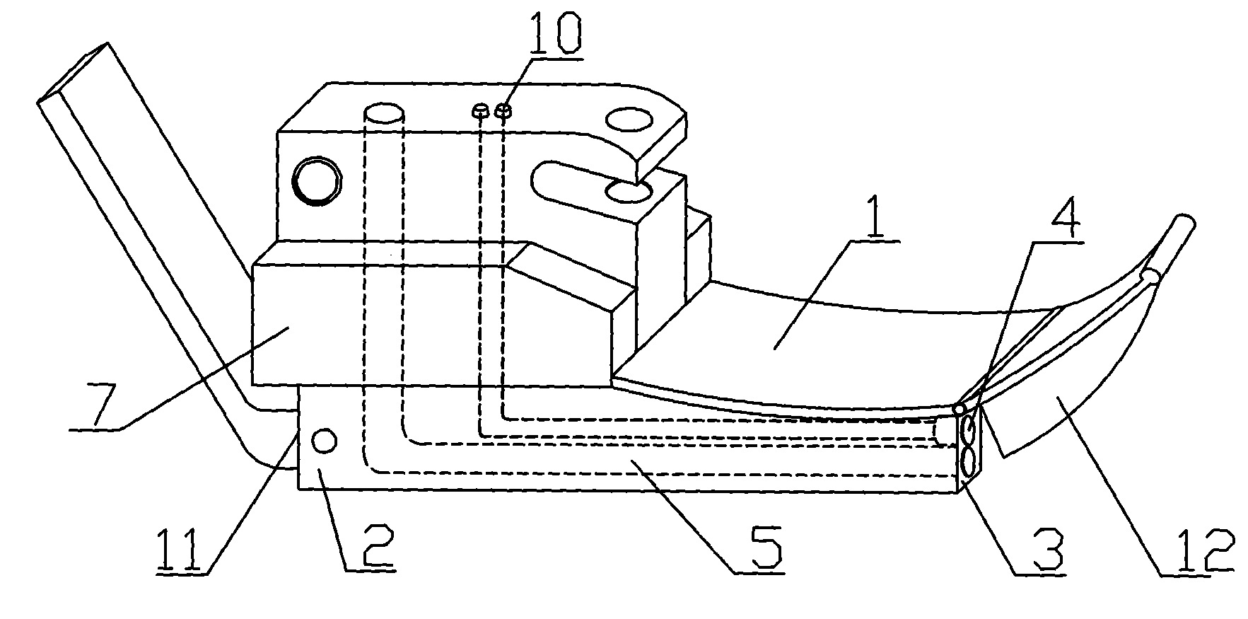
[0039] Example 3: Such as Figure 8 As shown, an anesthesia laryngoscope laryngoscope lens includes a laryngeal lens main body 1, which is a straight laryngeal lens, or as Picture 9 As shown, the laryngeal lens body 1 is a curved laryngeal lens, or as Picture 10 As shown, the laryngeal lens body 1 is a hook laryngeal lens; the laryngeal lens body 1 is composed of a lens blade 12 located below and a tailstock 7 installed above the rear end of the lens blade 12 and integrated with the lens blade 12; The bottom surface of the main body 1 lens blade 12 is provided with a support tube 2 with an open end and a hollow end. The open end 3 of the support tube faces the front end of the lens blade 12, and the closed end 11 of the support tube is placed at the rear end of the lens blade 12. The support tube 2 replaces the traditional laryngeal lens. The supporting part, when in use, the medical staff will lightly touch the supporting tube 2 on the patient's lower teeth, so that the front ...


PUM


Abstract

The invention discloses an anesthesia pharyngoscope mirror. The anesthesia pharyngoscope mirror comprises a pharyngoscope mirror body, wherein the pharyngoscope mirror body is composed of a mirror vane located at the lower portion and a tail seat which is installed on the rear end of the mirror vane and forms an integrated structure along with the mirror vane, a hollow supporting pipe with an open end is arranged on the bottom surface of the mirror vane, the open end of the supporting pipe faces the front end of the mirror vane, and the sealed end of the supporting pipe is located at the rear end of the mirror vane. A camera and an oxygen spraying pipe are arranged in the supporting pipe, and the front end of the camera and the front end of the oxygen spraying pipe are arranged at the open end of the supporting pipe. The anesthesia pharyngoscope mirror has the advantages that the supporting pipe used for protection is additionally arranged at the bottom of the anesthesia pharyngoscope mirror, a device is fixed inside the supporting pipe, industrial production is facilitated, and manufacturing cost is lowered; the supporting pipe effectively protects the device, impact and damage to the device are avoided, and the service life is prolonged; in the use process, the supporting pipe replaces a supporting part of a traditional pharyngoscope mirror; the supporting pope is convenient to clean and sterilize, and cross infection is prevented.

Description

Technical field: [0001] The invention relates to a medical appliance, in particular to an anesthesia laryngoscopy laryngoscope lens. Background technique: [0002] The existing straight or curved anesthesia laryngeal lens is equipped with a supporting part at the bottom of the rear end. When in use, the medical staff lightly touches the supporting part on the patient’s lower teeth to place the front end of the laryngeal lens into the oral cavity. To expose the glottis; and at the bottom of the laryngeal lens at the front end of the supporting member, any one of a camera, an oxygen supply tube, a drug delivery tube, or a sputum suction guide tube or any combination thereof is provided. The disadvantage is that when making the laryngeal lens, Due to the existence of supporting parts, the device is difficult to fix on the bottom of the laryngeal lens, which is inconvenient for industrial production and increases the manufacturing cost; the device is fixedly installed on the laryngea...

Claims


Application Information

Patent Timeline
Patent Type & Authority Applications(China)
IPC IPC(8): A61B1/267
CPCA61B1/267A61B1/015A61B1/05
Inventor 乌日娜舒妮
Owner SHANDONG YIHE MEDICAL TECH
Why Eureka
Try Eureka