Horizontal Flow Vertical Sludge Discharge Sedimentation Separation Device

一种沉淀分离、垂直排的技术,应用在沉降槽等方向,能够解决沉淀分离装置结构复杂、沉淀物易淤积在倾斜、堵塞排泥通道等问题,达到快速有效沉淀效果、解决斜板变形或坍塌、防止再悬浮的效果

Active Publication Date: 2016-01-13
ZHEJIANG DEAN TECH
View PDF7 Cites 0 Cited by
  • Summary
  • Abstract
  • Description
  • Claims
  • Application Information

AI Technical Summary

Problems solved by technology

[0004] The above-mentioned horizontal tube sedimentation and separation device partly improves the problem that the water flow and the direction of solid precipitation are easily disturbed, but the structure of the sedimentation and separation device is relatively complicated, and it also has high requirements for on-site installation, which limits its practicability; on the other hand, when the suspension When the types and sizes of the objects are relatively complicated, especially the large-sized suspended objects are easy to block the sludge outlet, and the sediment is easy to deposit on the inclined sludge discharge slide, blocking the sludge discharge channel; when the sedimentation is serious, it exceeds the bearing load of the horizontal pipe will cause the device to collapse

Method used


Image

  • Horizontal Flow Vertical Sludge Discharge Sedimentation Separation Device
  • Horizontal Flow Vertical Sludge Discharge Sedimentation Separation Device
  • Horizontal Flow Vertical Sludge Discharge Sedimentation Separation Device

Examples


Embodiment 1

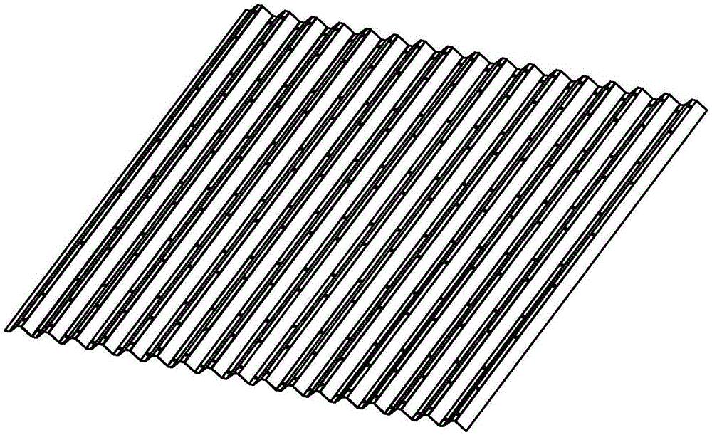
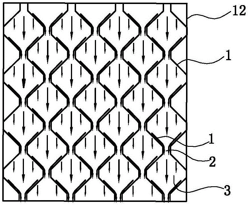
[0036] Such as Figure 1 to Figure 5 As shown, the horizontal flow vertical sludge discharge sedimentation separation device is installed in the sedimentation tank 12, which includes:

[0037] There are multiple corrugated plates 1, and these corrugated plates are arranged vertically relative to the horizontal plane, and the cross-section of the corrugated plates has a trapezoidal wave structure. The trapezoidal wave in this embodiment is an isosceles trapezoid, and the included angle α between the two waists and the corresponding valley bottom is 45°, and the width of the valley bottom is 1 cm. The width of the valley bottom can also select other sizes according to needs, usually Between 0.5 and 2 cm. The length of the two waists is 3 centimeters; the length of the waist can also be selected for other sizes as required, such as 2 to 3.5 centimeters.

[0038]In this embodiment, the surface of each corrugated pipe has a hydrophobic layer, thereby effectively reducing the resi...

Embodiment 2

[0045] Such as Figure 6 to Figure 8 As shown, the horizontal flow vertical sludge discharge and sedimentation separation device includes:

[0046] There are multiple corrugated plates 1, and these corrugated plates are arranged vertically relative to the horizontal plane, and the cross-section of the corrugated plates has a trapezoidal wave structure. The trapezoidal wave in this embodiment is an isosceles trapezoid, and the included angle α between the two waists and the corresponding valley bottom is 45°, and the width of the valley bottom is 1 cm. The width of the valley bottom can also select other sizes according to needs, usually Between 0.5 and 2 cm. The length of the two waists is 3 centimeters; the length of the waist can also be selected for other sizes as required, such as 2 to 3.5 centimeters.

[0047] In this embodiment, the surface of each corrugated pipe has a hydrophobic layer, thereby effectively reducing the resistance of the surface of the corrugated plat...

Embodiment 3

[0053] as above Figure 9 to Figure 13 As shown, the waveform of the cross section of the corrugated plate 14 in this embodiment is a triangular wave, such as Figure 10 As shown, a plurality of clamping holes 15 are arranged at intervals at sharp corners of the corrugated plate. In this embodiment, the distance between adjacent locking holes is 9 cm.

[0054] In the gap between adjacent corrugated plates 14, a plurality of partitions 16 are arranged at intervals, and these partitions run longitudinally between adjacent corrugated plates; The space between them is suitable, and it is also a zigzag structure to facilitate the positioning of the partition and the corrugated board when they are assembled; the rest of the partition is a linear plate structure, and the width of this partition is larger than that of the adjacent partition. The minimum distance between the plates is smaller than the maximum distance between adjacent partitions, that is, part of the edge of the part...


PUM


Abstract

The invention relates to a horizontal flow vertical sludge discharge and sedimentation separation device, which is characterized in that it includes a plurality of corrugated plates installed in the sedimentation tank, each of the corrugated plates is vertically arranged relative to the horizontal plane, and adjacent corrugated plates are arranged symmetrically and mutually There is a distance between them, and the minimum distance between adjacent corrugated plates is the mud discharge channel. Compared with the prior art, the present invention retains the advantages that the water flow and sediment discharge direction are perpendicular to each other and does not interfere with each other, avoids the disturbance between the horizontal flow and the sediment, prevents the sinking sludge from resuspension, and simultaneously The sludge discharge method is optimized, and a vertical sludge discharge slide is adopted. When the water flows horizontally through the water flow channel, the suspended matter collides with the frame of the water flow channel and settles quickly, slides along the frame into the sludge discharge channel, and directly settles to the sedimentation tank At the bottom, the sloping plate does not need to bear weight, thus solving the load-bearing problem caused by the excessive amount of sediment on the sloping plate.

Description

technical field [0001] The invention relates to the technical field of water treatment, and specifically refers to a horizontal flow vertical mud discharge sedimentation separation device for solid and liquid separation with supporting sedimentation facilities. Background technique [0002] The sedimentation and separation device is the basic unit in water treatment technology, and the research and development of high-efficiency sedimentation device has always been the focus of attention of those skilled in the art. At present, the sedimentation and separation device with inclined tube or inclined plate structure widely used in the sedimentation tank can effectively increase the sedimentation area and improve the sedimentation effect, but the direction of water flow is parallel to the direction of sedimentation, and the liquid and solid are prone to interference, which affects the sedimentation effect. ; It is easy to accumulate mud, block the inclined pipe or inclined plate...

Claims


Application Information

Patent Timeline
Patent Type & Authority Patents(China)
IPC IPC(8): B01D21/02
Inventor 俞建德
Owner ZHEJIANG DEAN TECH
Why Eureka
Try Eureka