Press roller cleaning mechanism of lithium battery pole piece rolling machine

The technology of a cleaning mechanism and rolling machine is applied to cleaning methods and utensils, cleaning methods using liquids, cleaning methods using tools, etc., which can solve the problems of unsatisfactory cleaning effect and low efficiency, and achieve consistency and ensure Uniform coating and reduced usage

Inactive Publication Date: 2014-03-26
万向电动汽车有限公司 +1
View PDF8 Cites 10 Cited by
  • Summary
  • Abstract
  • Description
  • Claims
  • Application Information

AI Technical Summary

Problems solved by technology

[0009] The purpose of the present invention is to overcome the unsatisfactory cleaning effect and low efficiency of the pressure roller cleaning method in the prior art, and provide a high-efficiency automatic pressure roller cleaning device that can realize continuous cleaning

Method used


Image

  • Press roller cleaning mechanism of lithium battery pole piece rolling machine
  • Press roller cleaning mechanism of lithium battery pole piece rolling machine
  • Press roller cleaning mechanism of lithium battery pole piece rolling machine

Examples


Embodiment 1

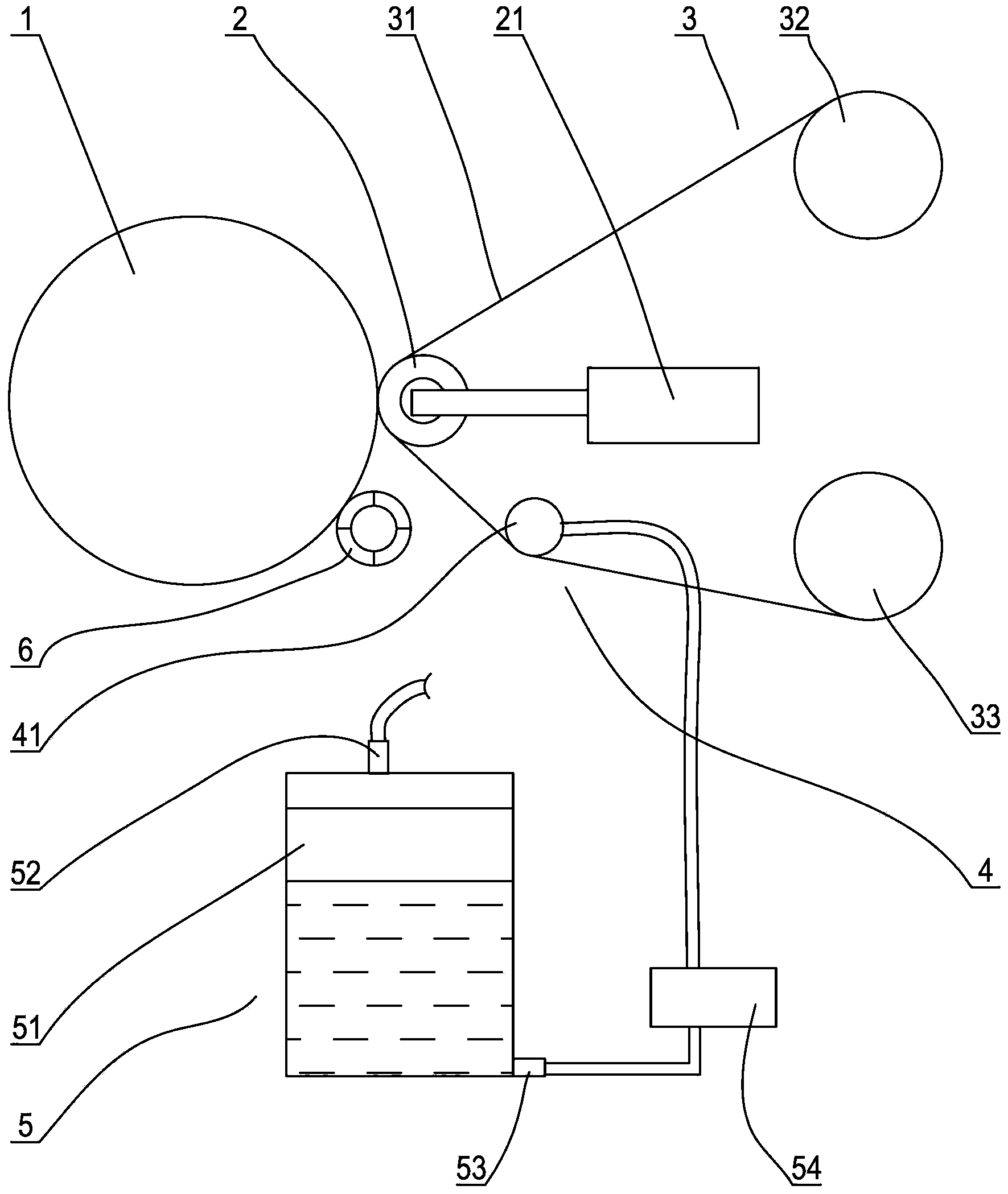
[0034] Embodiment 1: The roller cleaning mechanism of the lithium battery pole piece rolling machine of the present invention includes two cleaning units, which are respectively used to clean the upper and lower rollers, figure 1 Only one of the pressure rollers and the cleaning unit are shown in the figure. The cleaning unit includes a follower roller 2 arranged in parallel with the pressure roller 1, a coil conveying device 3 for taking and receiving the cleaning roll 31, and a cleaning roll for soaking the cleaning roll. The infiltration device 4.

[0035] The follower roller is located on the sending side of the pressure roller, and is pushed and translated by two cylinders 21 located on both sides, thereby having a working position pressing against the pressure roller and a standby position away from the pressure roller. In order to facilitate the control of the stroke of the cylinder piston rod and avoid the impact of the follower roller on the pressure roller, the end o...

Embodiment 2

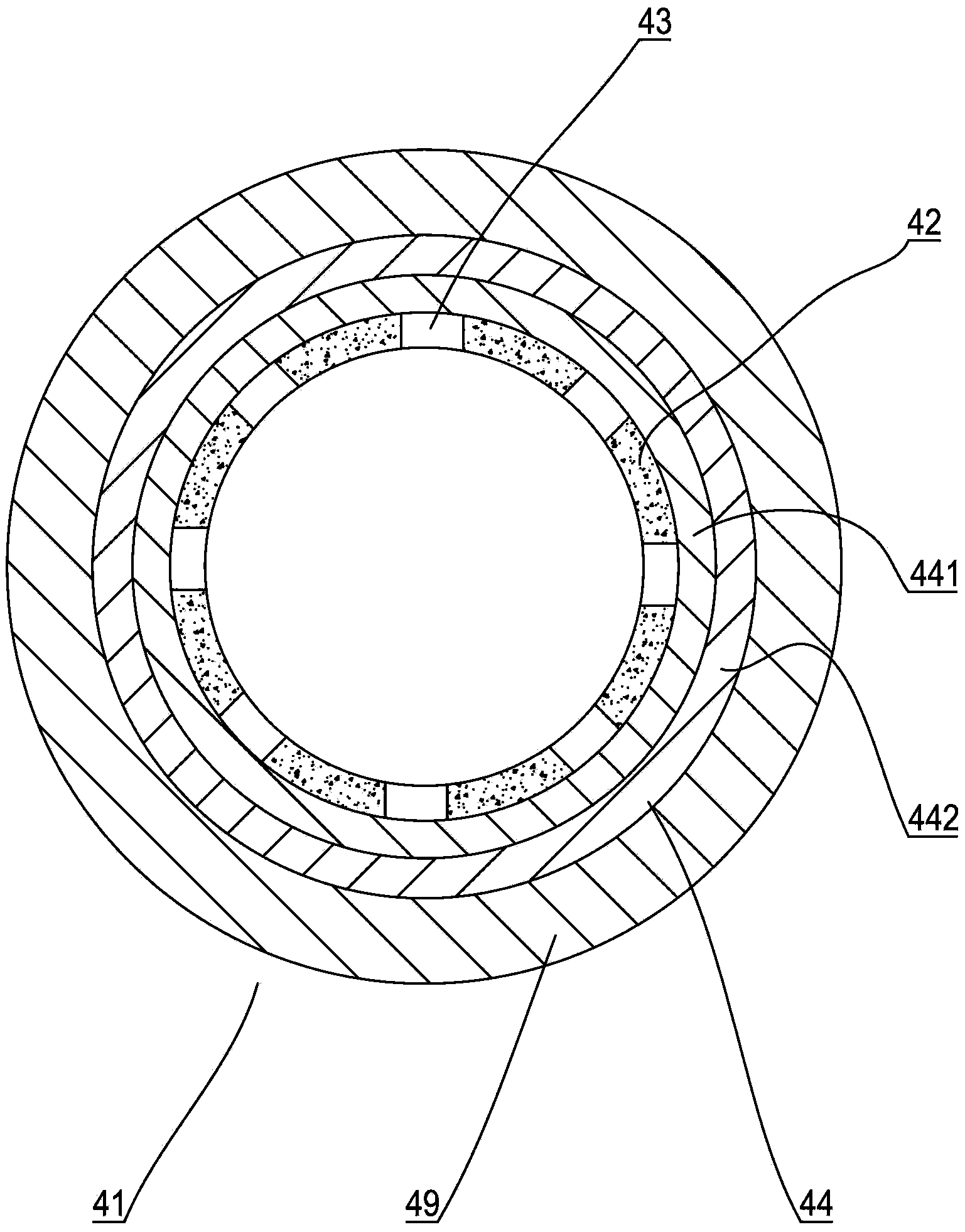
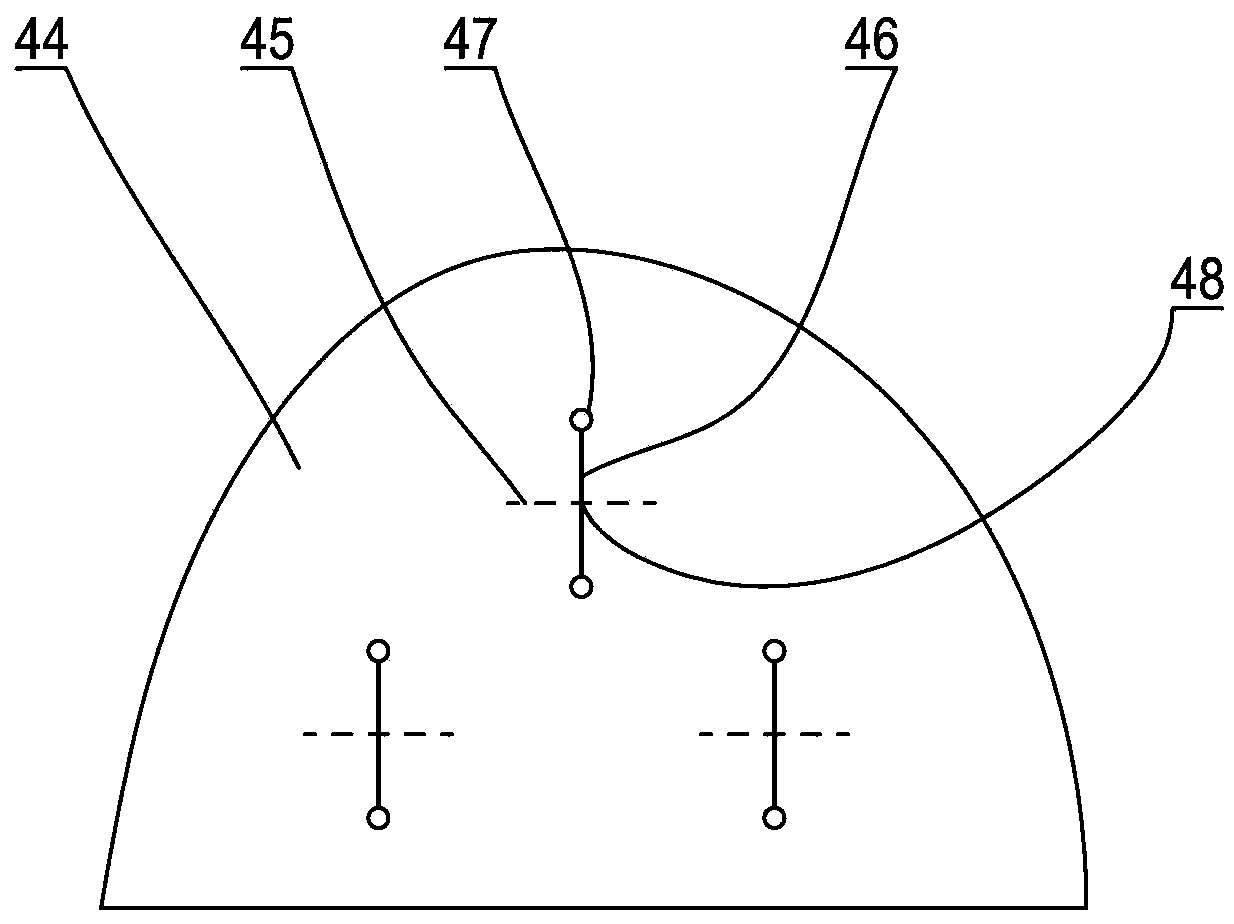
[0043] Embodiment two: if Image 6 As shown, the basic structure and cleaning process of this embodiment are the same as those of Embodiment 1, the difference is that a pinch roller 7 that is parallel and close to the soaking roller is added to the soaking device, and the cleaning roll is drawn from the soaking roll and the clamping roller. Passing through the nip between the pinch rolls, the dip roll is on the outside of the cleaning web, and the pinch roll, like the follower roll, is on the inside of the cleaning web. Such as Figure 7 As shown, the damping layer in the soaking roller adopts a single-layer structure, and the circumferential surface of the damping layer is provided with a number of evenly distributed outwardly convex seepage cylinders 443, and the seepage cylinders are embedded in the liquid seepage layer of the outer layer, and the seepage cylinders There is a liquid outlet hole 444 penetrating through the inner surface of the damping layer, and a number of...


PUM


Abstract

The invention discloses a press roller cleaning mechanism of a lithium battery pole piece rolling machine. The press roller cleaning mechanism comprises two cleaning units which are used for cleaning an upper press roller and a lower press roller respectively. The press roller cleaning mechanism is characterized in that each cleaning unit comprises a movable follow-up roller, a coiled material conveying device and an infiltrating device. The movable follow-up roller is arranged in parallel with the press rollers. The coiled material conveying device is used for collecting and releasing coiled materials, and the infiltrating device is used for infiltrating the cleaned coiled materials. The coiled material conveying device is provided with a coiled material delivering end and a coiled material collecting end, the cleaned coiled materials between the coiled material delivering end and the coiled material collecting end sequentially pass through the infiltrating device and the follow-up roller, and the follow-up roller is provided with a working position for compressing the press rollers and a standby position far away from the press rollers. The press roller cleaning mechanism can perform on-line continuous cleaning, and it is avoided that production efficiency is affected by a machine halt; automatic cleaning is convenient to achieve, and labor cost is reduced; uniformity of cleaning is high and the overall effect is good.

Description

[0001] This application is a divisional application of the invention patent application with application number 201110413650.5. The filing date of the original application: December 13, 2011. The invention name of the original application: an automatic cleaning device for pressure rollers. technical field [0002] The invention relates to lithium battery pole piece rolling equipment, in particular to a continuous automatic roller cleaning device for a lithium battery pole piece rolling machine. [0003] Background technique [0004] In the rolling process of lithium battery pole pieces used in electric vehicles, during the rolling operation process, due to the need for high compaction density and compression ratio, dust and material particles are easily bonded to the rolling machine during the rolling process. On the upper and lower pressure rollers of the machine, it will cause marks or even damage to the processed products. People usually use the following two methods to c...

Claims


Application Information

Patent Timeline
Patent Type & Authority Applications(China)
IPC IPC(8): B08B1/02
CPCB08B1/001B08B1/02B08B3/041B08B2203/0217
Inventor 董峰史离全周青山张景国茹永军郑丁
Owner 万向电动汽车有限公司
Why Eureka
Try Eureka