Charged sweeper

A live cleaning and insulated rotating shaft technology, applied in the direction of cleaning methods and utensils, chemical instruments and methods, cleaning methods using tools, etc., can solve the problems of not easy to control and use, and inconvenient operation, etc., to achieve convenient and easy control of the cleaning process , labor-saving operation and long charging time

Inactive Publication Date: 2014-03-26
STATE GRID SHANDONG ELECTRIC POWER
View PDF9 Cites 5 Cited by
  • Summary
  • Abstract
  • Description
  • Claims
  • Application Information

AI Technical Summary

Problems solved by technology

[0004] For this reason, the technical problem to be solved by the present invention is that the live cleaners in the prior art still require operators to carry them on their backs, and the operation is not convenient enough, and it is not easy to control and use, thereby providing a live cleaner that is easy to control and use. device

Method used


Image

  • Charged sweeper

Examples


Embodiment 1

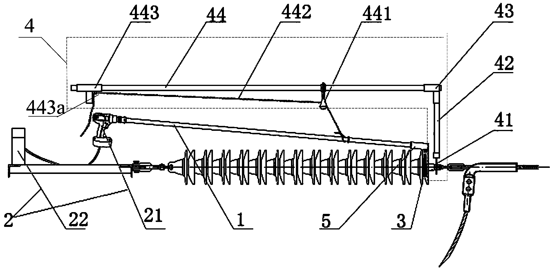
[0030] This embodiment provides a live cleaner, such as figure 1 As shown, it includes a main insulating transmission rod 1, which is provided with an insulating rotating shaft. One end of the insulating rotating shaft is connected to the power source 2, and the other end is connected to the brush body 3. The output power of the power source 2 drives the insulating rotating shaft to rotate and then drives the Described brush body 3 rotates. The live cleaner described in this embodiment also includes:

[0031] The positioning device 4 is used to fix the charged cleaner on the cleaning object.

[0032] The positioning device 4 includes:

[0033] One end of the positioning fork 41 is used to be fixed on the cleaning object, and the other end is connected to one end of the first insulating support rod 42 .

[0034] The other end of the first insulating support rod 42 is connected to one end of the second insulating support rod 44 through a bend 43 .

[0035] The pulley 441 is ...

Embodiment 2

[0041]On the basis of Embodiment 1, the live cleaner described in this embodiment, such as figure 1 As shown, the other end of the second insulating support rod 44 is provided with a handle 443 .

[0042] The positioning ring 443a is fixed on the handle 443 .

[0043] The insulating rope 442 passes through the pulley 441 and passes through the positioning ring 443a.

[0044] The live cleaner described in this embodiment, by adding a handle 443 with a positioning ring 443a on the second insulating rod, can facilitate the operator to manipulate the insulating rope 442 and facilitate the operator to adjust the cleaning position of the brush body 3 .

[0045] As a preferred implementation, the charged cleaner described in this embodiment, the power source 2, includes:

[0046] A handheld DC motor 21 and a lithium battery 22 are electrically connected between the handheld DC motor 21 and the lithium battery 22; the output shaft of the handheld DC motor 21 is connected to one end ...


PUM


Abstract

The invention relates to a charged sweeper. The charged sweeper comprises a main insulating drive rod. An insulating rotating shaft is arranged in the main insulating drive rod. One end of the insulation rotating shaft is connected with a power source, and the other end of the insulating rotating shaft is connected with a brush body. The power source outputs power to drive the insulating rotating shaft to rotate and then to drive the brush body to rotate. The charged sweeper further comprises a locating device. The locating device comprises a locating fork and a pulley. One end of the locating fork is fixed to a swept object, the other end of the locking fork is connected with one end of a first insulating supporting rod, and the other end of the first insulating supporting rod is connected with one end of a second insulating supporting rod through an elbow. The pulley is fixed to the second insulating supporting rod, one end of an insulating rope is fixedly connected with the main insulating drive rod, and the other end of the insulating rope penetrates through the pulley and then stretches out. The charged sweeper can be conveniently fixed to the swept object through the locating device, and therefore the weight of tools loaded by operators is reduced; the operators can easily control and utilize the charged sweeper to conduct sweeping operation, and work difficulties are reduced.

Description

technical field [0001] The invention relates to a live cleaner. Specifically, it is a live cleaner applied to high-voltage transmission lines. Background technique [0002] In the long-term operation of high-voltage transmission lines, such as porcelain bottles and silicone rubber insulators, the dust particles in the atmosphere will deposit on the surface to form a dirty layer. When the climate is dry, the resistance of the dirty layer is very large, and the insulation performance will not be reduced. However, under fog, dew, light rain, snow and other meteorological conditions, after the electrolyte in the dirty layer gets wet, its surface conductivity increases, resulting in a decrease in insulation performance, and the ash in it will retain moisture, promoting the dirty layer to get wet and dissolve More electrolyte, causing flashover discharge on the wetted surface of the insulation, referred to as pollution flashover. Pollution flashover of tension string porcelain b...

Claims


Application Information

Patent Timeline
Patent Type & Authority Applications(China)
IPC IPC(8): B08B1/04
CPCB08B1/002B08B1/04
Inventor 乔绪山毕崇峻李磊孙恩德陈永平
Owner STATE GRID SHANDONG ELECTRIC POWER
Why Eureka
Try Eureka