Punching manipulator

A technology of manipulators and cabinets, applied in the field of stamping devices, can solve problems such as work-related accidents, hand-crushing and disability, and insecurity, and achieve the effects of speeding up machine operation, saving machine investment, and eliminating work-related disability accidents.

Inactive Publication Date: 2014-03-26
冯华仁
View PDF4 Cites 11 Cited by
  • Summary
  • Abstract
  • Description
  • Claims
  • Application Information

AI Technical Summary

Problems solved by technology

[0002] The current punching equipment is generally operated manually when stamping parts, that is, manually put the workpiece on the mold of the punching machine. It is very unsafe to place and take out workpieces by hand. Work-related accidents often occur, causing people to be crushed and disabled.

Method used


Image

  • Punching manipulator
  • Punching manipulator
  • Punching manipulator

Examples


Embodiment Construction

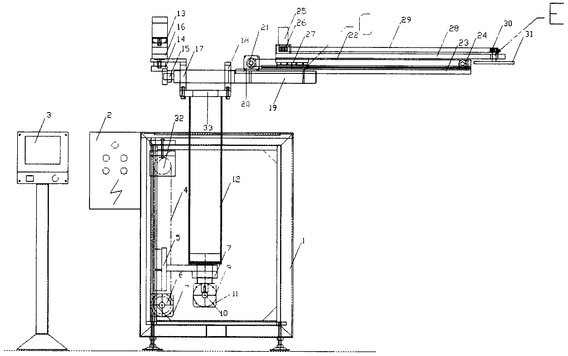
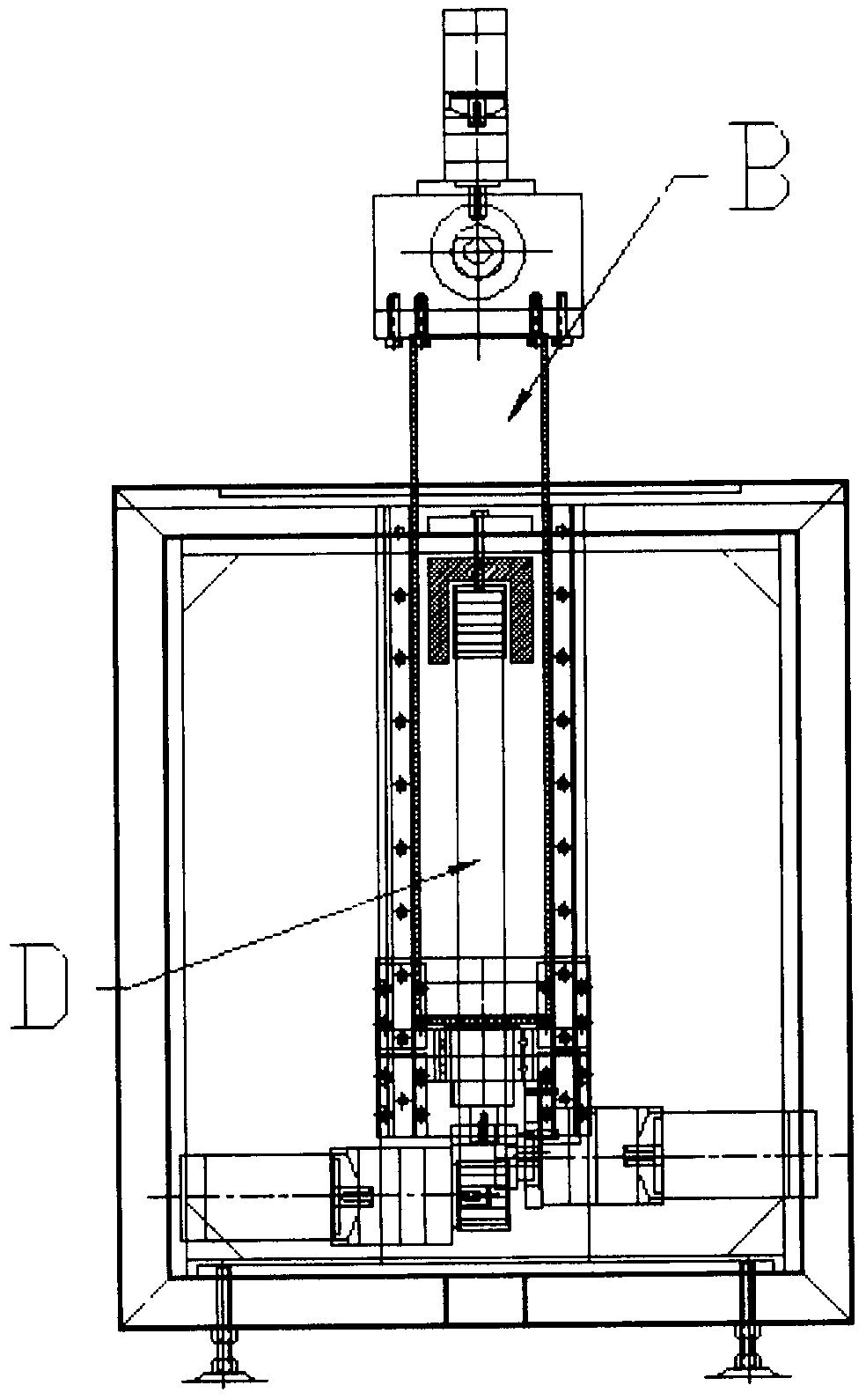
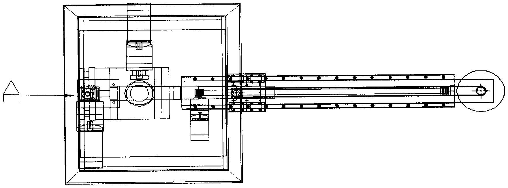
[0011] Below in conjunction with accompanying drawing, content of the invention will be further described:

[0012] refer to Figure 1-Figure 3 As shown, the stamping manipulator includes a cabinet 1, and the cabinet 1 is provided with a power distribution cabinet 2, and the cabinet 1 includes a first synchronous wheel 32 and a second synchronous wheel 32 that are surrounded by a first synchronous belt 4 from top to bottom. A synchronous wheel 6, the first synchronous belt 4 is also provided with an upper and lower sliding plate 5, the first servo motor 7 is driven to connect the second synchronous wheel 6, and the upper and lower sliding plates 5 are in phase with the swing arm support plate 7 in the cabinet 1 connection, the swing arm support plate 7 is driven and connected with the second servo motor 9 through two adapted first taper gear sets (10; 11), and the swing arm support plate 7 is also connected with the swing arm extending into the cabinet 1 One end of the column...


PUM


Abstract

A punching manipulator comprises a vertical moving mechanism, a horizontal moving mechanism, a turning moving mechanism, a swinging moving mechanism and an executing end rotating moving mechanism. The defect that human hands are broken and crippled due to frequently-occurring industrial accidents in the prior art is effectively overcome.

Description

technical field [0001] The invention relates to the technical field of stamping devices, in particular to a stamping manipulator. Background technique [0002] The current punching equipment is generally operated manually when stamping parts, that is, manually put the workpiece on the mold of the punching machine. It is very unsafe to place and take out workpieces by hand. Work-related accidents often occur, causing people to be crushed and disabled. Contents of the invention [0003] The purpose of the present invention is to provide a stamping manipulator, including vertical motion mechanism, horizontal motion mechanism, flipping motion mechanism, swing arm motion mechanism, and execution end rotary motion mechanism that are connected to each other, effectively avoiding the frequent work-related injuries in the prior art Accidents crush the defects of manpower and disable them. [0004] In order to overcome the deficiencies in the prior art, the present invention provi...

Claims


Application Information

Patent Timeline
Patent Type & Authority Applications(China)
IPC IPC(8): B21D43/10B21D45/00B25J9/10B25J15/06
Inventor 冯华仁
Owner 冯华仁
Why Eureka
Try Eureka