Turning tool device for turning narrow and deep end face groove with shaft

A technology with end faces and shafts, which is applied in the direction of lathe tools, turning equipment, manufacturing tools, etc. It can solve the problems of weakened tool strength and rigidity, low turning tool strength, and easily damaged parts, etc., and achieves blade regrinding Good, the strength and rigidity of the cutter bar are good, and the effect of convenient clamping

Active Publication Date: 2014-03-26
TIANJIN SAIXIANG M&E ENG CO LTD
View PDF6 Cites 0 Cited by
  • Summary
  • Abstract
  • Description
  • Claims
  • Application Information

AI Technical Summary

Problems solved by technology

[0002] in processing such as figure 1 For parts with a shaft on the end face shown and a narrow and deep end face groove, the turning process usually adopts the following methods: figure 2 The structure of the tool shown; the feature of this end face annular groove is that the width a of the groove is small, for example a<2mm, and the depth b is much larger than the width a, especially the ΦA axis protruding from the end face, so that The protruding part of the tool is lengthened, and the strength and rigidity of the tool are weakened. When the turning method is used for processing, the diameter of the tool bar of the turning tool must be smaller than a, and the protruding length of the tool bar must be greater than b. The length-to-diameter ratio of the protruding part of the tool bar It must be greater than b / a, resulting in low strength of the turning tool, poor rigidity, easy to break, and easy to damage parts, so it is necessary to improve

Method used


Image

  • Turning tool device for turning narrow and deep end face groove with shaft
  • Turning tool device for turning narrow and deep end face groove with shaft
  • Turning tool device for turning narrow and deep end face groove with shaft

Examples


Embodiment Construction

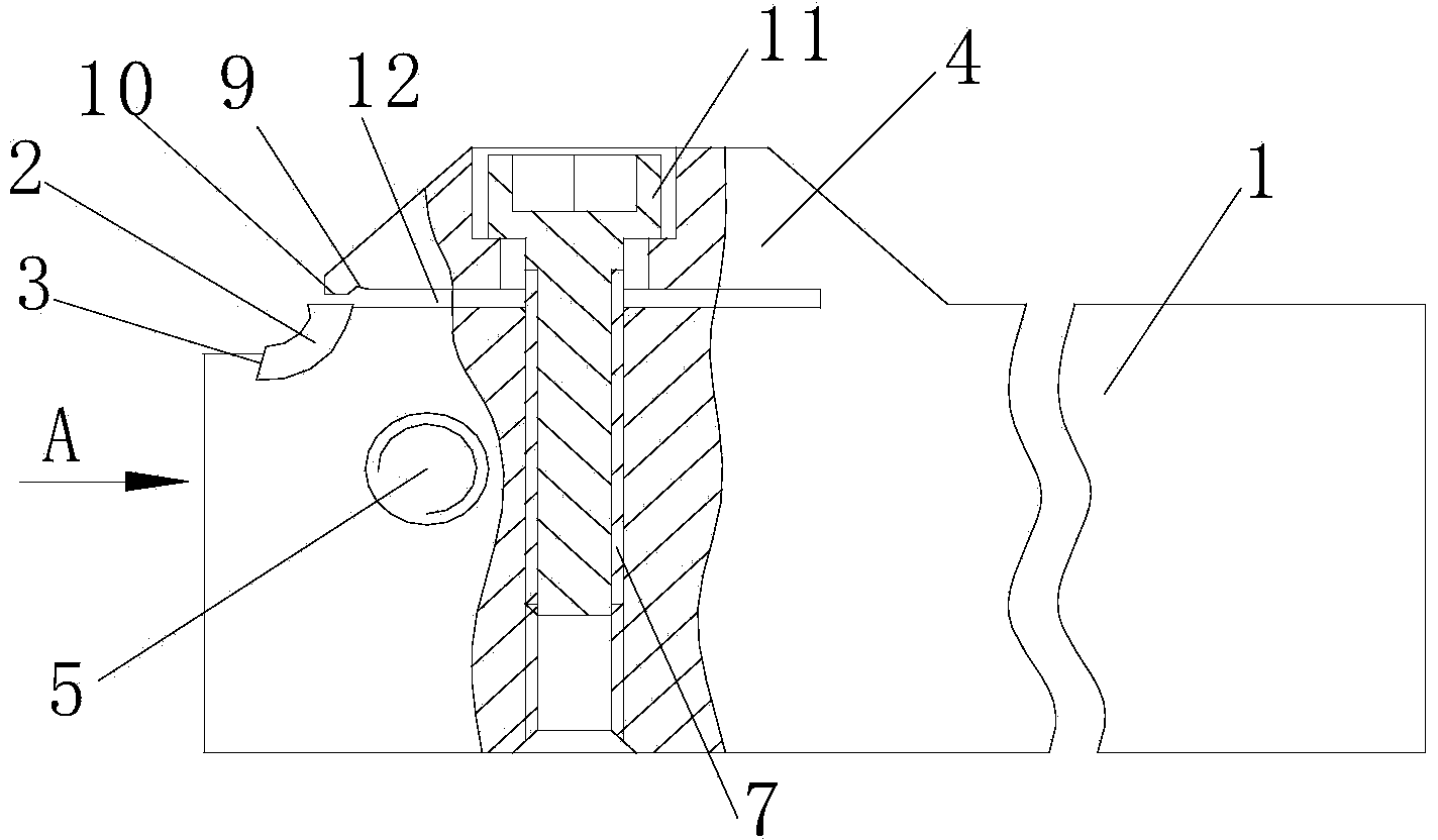
[0033] Attached below Figure 1-11 An embodiment of the present invention is described.

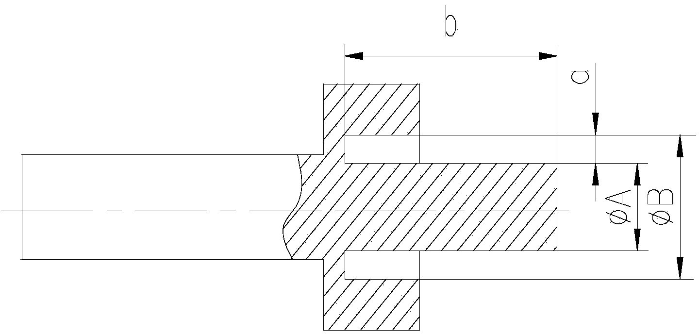
[0034] Turning tool device with narrow and deep grooves on the end surface of the shaft, which has a tool bar 1 and a blade 2. The tool bar 1 is in the shape of a cuboid as a whole. The rear end of the tool bar 1 is clamped with the tool holder as one. Groove 3, the overall shape of the blade 2 is a concave ring, the blade 2 is included in the groove 3 and both ends of the blade 2 protrude from the groove 3, the upper end surface of the knife rod 1 is shaped on a pressing plate 4, and the pressing plate 4 passes through the sinking The head screw 11 compresses the blade 2 in the groove 3. Specifically, the pressure plate 4 and the cutter bar 1 are of an integrated structure, and a pressure groove 12 is formed between the front end of the press plate 4 and the upper end surface of the cutter bar 1, wherein, The upper end surface of the cutter bar 1 is formed with a threaded hole II7, and ...


PUM


Abstract

The invention provides a turning tool device for turning a narrow and deep end face groove with a shaft. The turning tool device is provided with a cutter rod and a cutter blade, wherein the cutter rod is rectangular on the whole, the rear end of the cutter rod and a cutter frame are assembled to form a whole in a clamped mode, the front end of the cutter rod is provided with a groove, the cutter blade is of a concave annular shape on the whole, the cutter blade is held in the groove, the two ends of the cutter blade both extend out of the groove, the upper end face of the cutter rod is provided with a pressing plate, the pressing plate presses the cutter blade into the groove through a sunk screw, the side face of the cutter rod is further provided with a threaded hole I, a screw rod is screwed into the threaded hole I and is locked through a nut, and the end face of the nut abuts against the rear end portion of the cutter blade. The turning tool device is a combination piece on the whole, each single piece is a machined piece, the cutter rod and the cutter blade do need to be welded, when the cutter blade is severely abraded or broken, what is needed is to grind a front corner and a rear corner from the broken portion of the cutter blade, and then the cutter blade can be used; the strength and the rigidity of the cutter rod are good; the abrasion resistance of the cutter blade is good; the extending length of the cutter rod is easy to control; the repeated clamping error is small; the pressing plate and the cutter rod are of an integrated structure, and clamping is easy to achieve; the service life is greatly prolonged, manufacturing is easy to achieve and cost is low.

Description

technical field [0001] The invention belongs to the technical field of mechanical processing, and in particular relates to a turning tool device for turning narrow and deep grooves on the end surface of a belt shaft. Background technique [0002] in processing such as figure 1 For parts with a shaft on the end face shown and a narrow and deep end face groove, the turning process usually adopts the following methods: figure 2 The structure of the tool shown; the feature of this end face annular groove is that the width a of the groove is small, for example a<2mm, and the depth b is much larger than the width a, especially the ΦA axis protruding from the end face, so that The protruding part of the tool is lengthened, and the strength and rigidity of the tool are weakened. When the turning method is used for processing, the diameter of the tool bar of the turning tool must be smaller than a, and the protruding length of the tool bar must be greater than b. The length-to-d...

Claims


Application Information

Patent Timeline
Patent Type & Authority Applications(China)
IPC IPC(8): B23B27/00
CPCB23B27/1603
Inventor 史厚民吕芸芬
Owner TIANJIN SAIXIANG M&E ENG CO LTD
Why Eureka
Try Eureka