Die for die-cutting machine

A die-cutting machine and mold technology, applied in the direction of perforating tools, manufacturing tools, metal processing, etc., can solve the problems of increased production costs, unspecified dimensions, waste of materials, etc., and achieve the goal of improving precision and quality, and accurate positioning Effect

Inactive Publication Date: 2014-03-26
SUZHOU DONGFU ELECTRONICS
View PDF11 Cites 0 Cited by
  • Summary
  • Abstract
  • Description
  • Claims
  • Application Information

AI Technical Summary

Problems solved by technology

[0002] When the general die-cutting machine is processing the material, there is no certain regulation on the size of the material, so it is easy to cause waste of material during processing. At the same time, when processing the material, it often does not control the material, so that The machine is processed according to the set distance. This design is easy to produce too much waste for production, which increases production costs.

Method used


Image

  • Die for die-cutting machine
  • Die for die-cutting machine
  • Die for die-cutting machine

Examples


Embodiment Construction

[0013] The present invention is described below in conjunction with accompanying drawing.

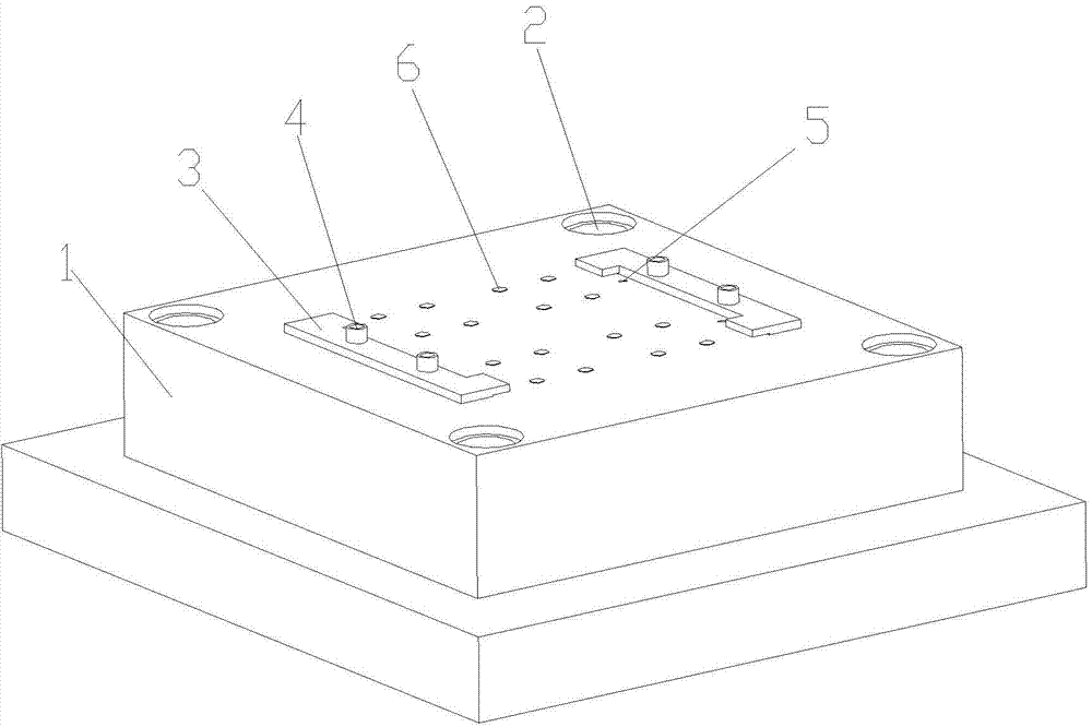
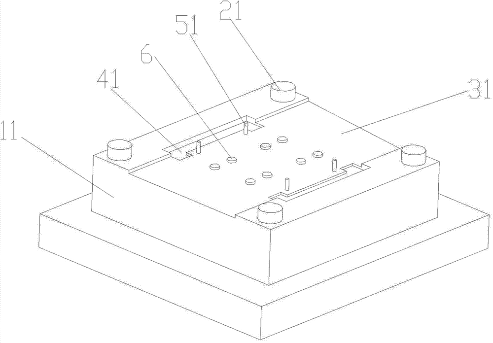
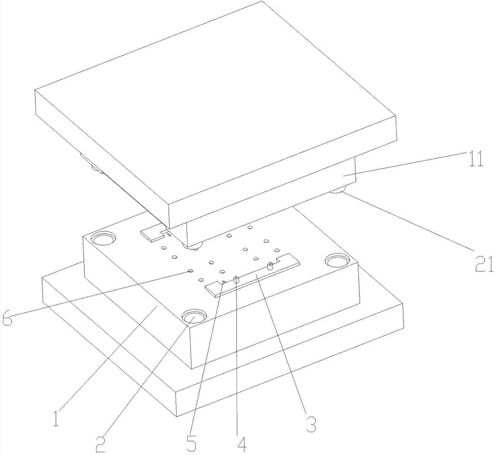
[0014] attached Figure 1-3 It is a mold for a die-cutting machine according to the present invention, including a male die and a female die, the male die includes a male template 1, and the four corners of the male template 1 are provided with positioning grooves 2; the male template 1 is provided with Two matched clamping plates 3; the clamping plates 3 are fixed by adjusting bolts 4; positioning holes 5 are provided on the opposite inner sides of the two clamping plates 3; There is a gap; the female mold includes a female template 11, and the four corners of the female template 11 are provided with positioning columns 21 that cooperate with the positioning groove 2 on the male template 1; the middle part of the female template 11 is a concave step 31; the lower Both sides of the concave step 31 are also provided with a clamp groove 41 matched with the clamp 3; the female template 11...


PUM


Abstract

The invention discloses a die for a die-cutting machine. The die comprises a male die and a female die. The male die comprises a male die plate, wherein positioning grooves are formed in four corners of the male die plate; the male die plate is provided with two clamping plates matched with each other; the clamping plates are fixed through adjusting bolts; the opposite inner sides of the two clamping plates are provided with positioning holes; gaps are formed between the opposite inner sides of the two clamping plates and the male die plate. The female die comprises a female die plate, wherein positioning posts matched with the positioning grooves in the male die plate are arranged at four corners of the female die plate; a concave step is arranged in the middle of the female die plate; clamping plate grooves matched with the clamping plates are further formed in two sides of the concave step; positioning ejector pins matched with the positioning holes are arranged at the positions, on the inner sides of the clamping plate grooves, of the female die plate. According to the die for the die-cutting machine, by means of design of the clamping plates, the clamping plate grooves, the positioning ejector pins, the positioning holes, the concave step and the gaps formed between the opposite inner sides of the two clamping plates and the male die plate, the die can be used for effectively positioning and fixing materials during machining; during machining, accurate positioning can be achieved, the routes of the materials can be controlled, and precision and quality of products are improved.

Description

technical field [0001] The invention relates to a mold for a die-cutting machine, which belongs to the technical field of machine molds. Background technique [0002] When the general die-cutting machine is processing the material, there is no certain regulation on the size of the material, so it is easy to cause waste of material during processing. At the same time, when processing the material, it often does not control the material, so that The machine is processed according to the set distance. Such a design is easy to produce too much waste and increase production costs. Contents of the invention [0003] In view of the above-mentioned technical problems, the object of the present invention is to propose a mold for die-cutting machine with accurate positioning and stable material travel. [0004] The technical solution of the present invention is realized in the following way: a die-cutting machine mold includes a male die and a female die, the male die includes a ma...

Claims


Application Information

Patent Timeline
IPC IPC(8): B26F1/14B26D7/01B21D28/34B21D43/00
Inventor 杜宏举
Owner SUZHOU DONGFU ELECTRONICS
Why Eureka
Try Eureka