Splicing tank

A technology for assembling tanks and tank walls, applied in packaging, transportation, packaging, containers, etc., can solve the problems of long construction period, non-removable transfer, waste of resources, etc. and maintenance costs, the effect of protecting the environment

Active Publication Date: 2014-03-26
BC P INC CHINA NAT PETROLEUM CORP +1
View PDF7 Cites 1 Cited by
  • Summary
  • Abstract
  • Description
  • Claims
  • Application Information

AI Technical Summary

Problems solved by technology

[0003] The present invention provides an assembled tank, which overcomes the deficiencies of the above-mentioned prior art, and can effectively solve the long construction period and high cost of existing large sewage tanks. , cannot be disassembled and transferred, needs to be backfilled after not in use, and wastes resources

Method used


Image

  • Splicing tank
  • Splicing tank
  • Splicing tank

Examples


Embodiment Construction

[0023] The present invention is not limited by the following examples, and specific implementation methods can be determined according to the technical solutions of the present invention and actual conditions.

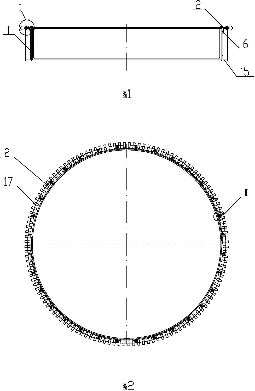
[0024] In the present invention, for the convenience of description, the description of the relative positional relationship of each component is based on the description attached to the description. figure 1 For example, the positional relationship of front, back, up, down, left, right, etc. is based on the attached figure 1 determined by the layout direction.

[0025] Below in conjunction with embodiment and accompanying drawing, the present invention will be further described:

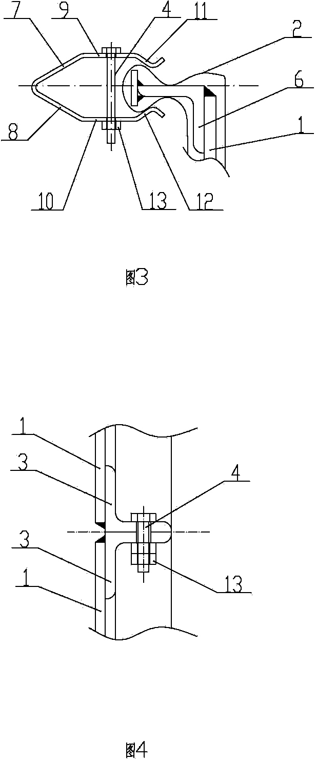
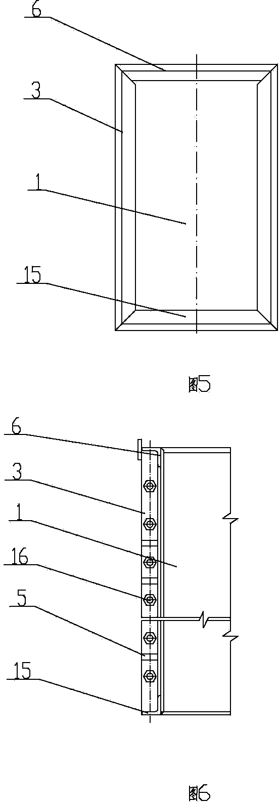
[0026] as attached figure 1 , 2 As shown, the assembled tank includes a tank wall and a bladder 2 with an open upper end. The tank wall is spliced ​​by at least two wall panels 1. The bladder 2 is located inside the tank wall. The upper end of the bladder 2 is fixed on the up...


PUM


Abstract

The invention relates to a technical field of oil-gas field development and discloses a splicing tank. The splicing tank comprises a tank wall and a sac body with the upper end opened. The tank wall is spliced by at least two wall boards, the sac body is located in the tank wall, and the upper end of the sac body is fixed to the edge of the upper end of the tank wall. The splicing tank is reasonable and compact in structure and convenient to use. The tank wall is spliced by a plurality of splicing boards and the sac body is laid in the tank wall so that rapid installation can be achieved. Meanwhile, the splicing tank is convenient to detach and transfer, capable of being reused, short in construction period, low in cost, good in sealing performance and capable of avoiding use of reinforced concrete, reducing resource waste, construction cost and maintaining cost, protecting the environment and improving economical benefits and social benefits.

Description

technical field [0001] The invention relates to the technical field of oil and gas field development, and relates to an assembled tank. Background technique [0002] Fracturing technology is an important part of the oil and gas field development process. The purpose of fracturing is mainly to improve the permeability of oil and gas layers and remove plugging. Fracturing technology occupies an irreplaceable position in new well testing, oil well tapping in old areas and single well stimulation, so it is widely used. However, a large amount of flowback waste fluid will be generated during the fracturing operation. At present, almost all oil and gas fields adopt crude oil sewage pools in remote areas of oil fields for centralized storage. The main structures of crude oil sewage pools are reinforced concrete structures. Large-scale sewage pools have long construction periods, high costs, and cannot be disassembled and transferred. Backfilling causes waste of resources. Co...

Claims


Application Information

Patent Timeline
Patent Type & Authority Applications(China)
IPC IPC(8): B65D88/52B65D90/08B65D90/00
Inventor 章敬凌勇崔玉淼黄强戚亚明张斌李伟权王林阳李阳李佳琦江洪陈仙江
Owner BC P INC CHINA NAT PETROLEUM CORP
Why Eureka
Try Eureka