
Elevator multi-fold door operator device

A door operator and elevator technology, applied in the field of elevator components, can solve the problems of complex structure, danger and high cost, and achieve the effects of simple and compact structure, preventing door panels from falling off, and low production cost

Inactive Publication Date: 2014-03-26
NINGBO XINDA ELEVATOR FITTINGS FACTORY
View PDF8 Cites 12 Cited by
  • Summary
  • Abstract
  • Description
  • Claims
  • Application Information

AI Technical Summary

Problems solved by technology

[0002] Existing multi-folding door machine devices for elevators, such as the centrally divided double-folding door machine device, have two main modes of movement for the multi-door panels: (1) The door machine directly uses crank arm linkage to open and close the door. This structure is bulky and the operation noise (2) The door machine uses a synchronous belt to drive the main shutter door panel, and the movement of the other door panels is driven by a linkage wire rope installed between the fast and slow door hanging panels
The structure is complex. Due to the small space between the fast and slow door hanging plates, it is difficult to install the complex wire rope transmission structure pre-tightening, and it is prone to operation interference faults and difficult to adjust. In addition, due to the small space between the fast and slow door hanging plates, resulting in The guide rail cannot be strengthened, and the guide rail is variable and easy to fall off during use, causing danger

Method used


Image

  • Elevator multi-fold door operator device
  • Elevator multi-fold door operator device
  • Elevator multi-fold door operator device

Examples


Embodiment 1

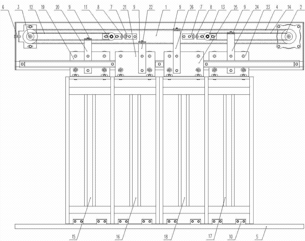
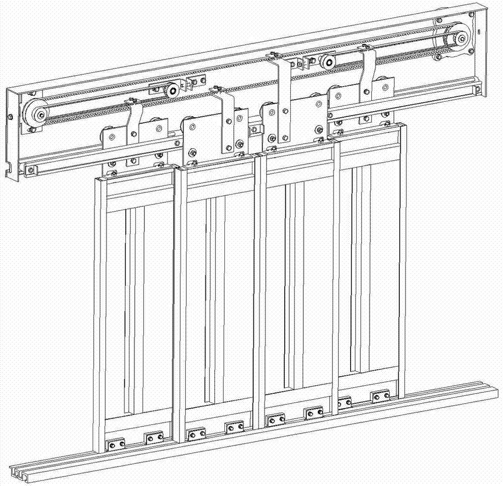
[0041] like figure 1 , figure 2 , image 3 , Figure 4 As shown, the double-folding door machine device in this embodiment includes a door machine bottom plate assembly 1, a drive motor 2, a main pulley assembly 3, a main timing belt 4, two sets of left and right small pulley assemblies and a small timing belt (left Small pulley assembly 11, left small synchronous belt 12, right small pulley assembly 13, right small synchronous belt 14), two door panels on the left and right sides (left slow door panel 15, left shutter panel 16, right slow door panel 17 , right shutter plate 18), left slow door hanging plate assembly 19, left shutter hanging plate assembly 21, right shutter hanging plate assembly 23, right slow door hanging plate assembly 25, left slow door hanging arm 20, left shutter hanging arm 22, Right shutter boom 24, right slow door boom 26, door machine sill 5.

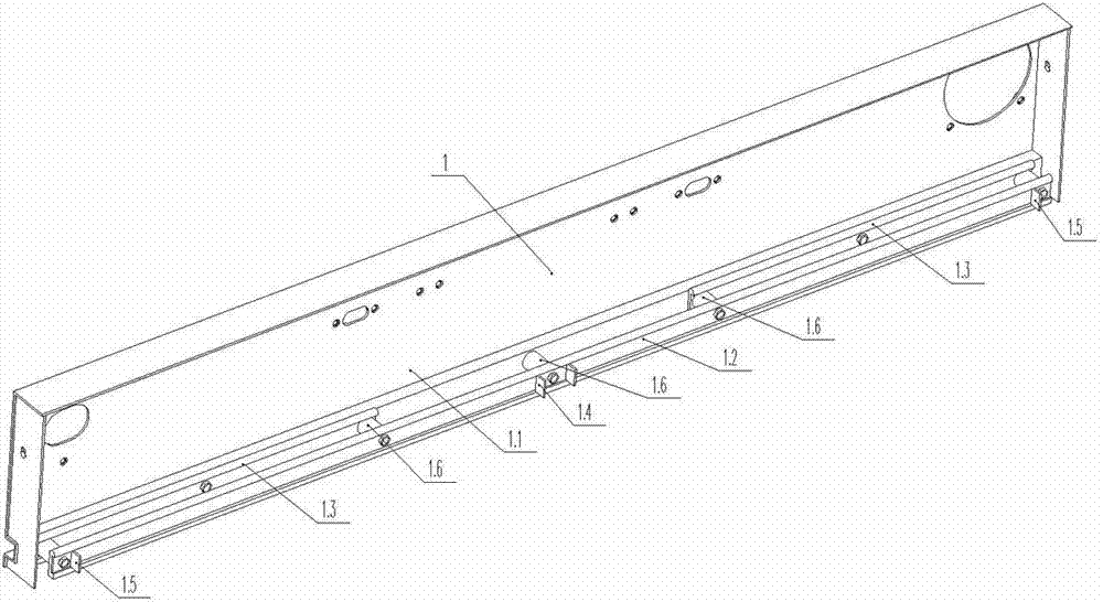
[0042] The door machine base plate assembly 1 includes a door machine base plate 1.1, a long guide rai...

Embodiment 2

[0050] like Figure 5 As shown, the unilateral double-folding door machine device in this embodiment includes a door machine bottom plate assembly 1, a drive motor 2, a main pulley assembly 3, a main timing belt 4, a small main pulley assembly 31, a small timing belt 32, and a slow door plate 33 , shutter plate 34, slow door hanger assembly 35, slow door arm 36, shutter hanger assembly 37, shutter arm 38, door machine sill 5.

[0051] The door machine base plate assembly 1 includes a door machine base plate 1.1, a long guide rail, a short guide rail, a baffle plate for fully opening the door, a baffle plate for fully closing the door, and a sleeve. The straight line where the short guide rail is located is parallel to the long guide rail on the same horizontal plane. The door machine bottom plate assembly 1 is used for supporting the whole door machine and installing other parts of the door machine. The door machine sill 5 is stationary relative to the door machine floor asse...

Embodiment 3

[0059] like Figure 6As shown, the three-fold door machine device in this embodiment includes a door machine bottom plate assembly 1, a drive motor 2, a main pulley assembly 3, a main timing belt 4, four groups of left and right small pulley assemblies and a small timing belt (left Small pulley assembly 41, left small timing belt 42, left middle pulley assembly 43, left middle timing belt 44, right small pulley assembly 45, right small timing belt 46, right middle pulley assembly 47, right middle timing belt 48 ), three door panels on the left and right sides (left slow door panel 49, left middle door panel 50, left shutter panel 51, right slow door panel 54, right middle door panel 53, right shutter panel 52), door machine sill 5.

[0060] The door machine base plate assembly 1 includes a door machine base plate 1.1, a long guide rail, two short guide rails on the left and right, and two middle guide rails on the left and right. The two short guide rails are located on the sa...


PUM


Abstract

The invention provides an elevator multi-fold door operator device. The elevator multi-fold door operator device comprises a door operator base plate assembly (1), a driving motor (2), a main belt pulley assembly (3), a main synchronous belt (4), at least one secondary synchronous belt, at least one secondary belt pulley assembly, door sheets and a door operator sill (5), wherein at least one side of a door operator body is provided with at least two door sheets, the door operator base plate assembly (1) comprises a door operator base plate (1.1), one end of the main synchronous belt (4) surrounds the driving motor (2), the other end of the main synchronous belt (4) surrounds the main belt pulley assembly (3), one end of the secondary synchronous belt surrounds the driving motor (2) or the main belt pulley assembly (3), the other end of the secondary synchronous belt surrounds the secondary belt pulley assembly, the drive speed of the secondary synchronous belt is different from that of the main synchronous belt (4), the top ends of the door sheets are connected to the main synchronous belt (4) or the secondary synchronous belt, and the door sheets on the same side are different in operation speed. According to the elevator multi-fold door operator device, the structure is simple, reinforcing processing can be carried out on guide rails due to the fact that a space is provided, use is safe, energy consumption is low, and the service life is long.

Description

technical field [0001] The invention relates to the technical field of elevator components, in particular to an elevator multi-folding door machine device. Background technique [0002] Existing multi-folding door machine devices for elevators, such as the centrally divided double-folding door machine device, have two main modes of movement for the multi-door panels: (1) The door machine directly uses crank arm linkage to open and close the door. This structure is bulky and the operation noise (2) The door machine uses a synchronous belt to drive the main shutter door panel, and the movement of the other door panels is driven by the linkage wire rope installed between the fast and slow door hanging panels. The structure is complex. Due to the small space between the fast and slow door hanging plates, it is difficult to install the complex wire rope transmission structure pre-tightening, and it is prone to operation interference faults and difficult to adjust. In addition, du...

Claims


Application Information

Patent Timeline
IPC IPC(8): B66B13/08
Inventor 张道仓
Owner NINGBO XINDA ELEVATOR FITTINGS FACTORY
Learn More