High-low ridge stilling pool achieving double-layer disperse energy dissipation
A technology of decentralized energy dissipation and stilling pools, which is applied in water conservancy projects, sea area engineering, coastline protection, etc., can solve problems affecting the normal operation of flood discharge structures, damage to the structure of stilling pools, and unstable flow states, so as to avoid air pollution. Effects of reducing cavitation, protecting safety, and improving stress conditions
- Summary
- Abstract
- Description
- Claims
- Application Information
AI Technical Summary
Problems solved by technology
Method used
Image

Examples
Embodiment 1
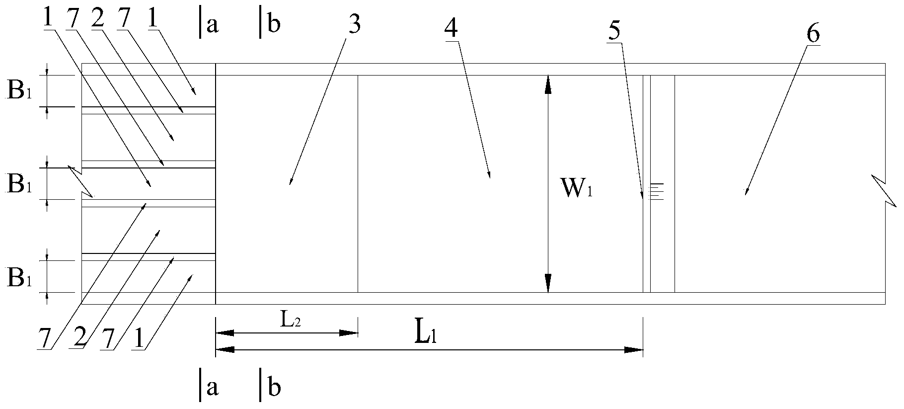
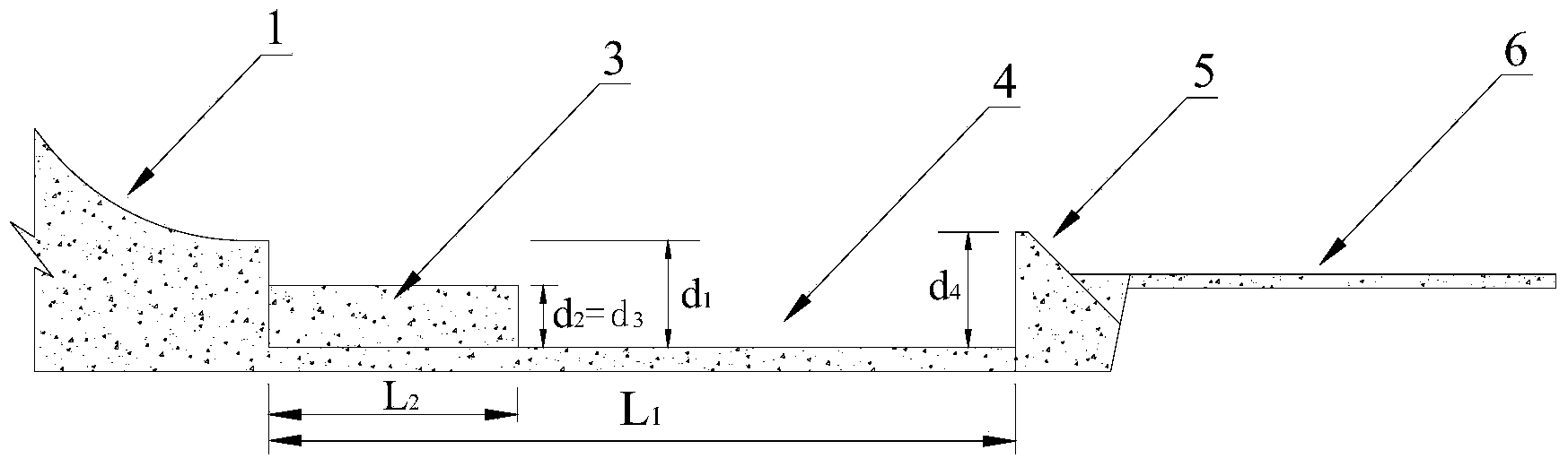
[0061] The structure of the high and low ridge stilling pools of the double-layer dispersed energy dissipation in Embodiment 1 of the present invention is as follows figure 1 , image 3 , Figure 4 , Figure 5 , Figure 7 As shown, it includes the water flow inlet section of the falling sill, the upper stilling basin 3 connected to the water flow inlet section, the lower stilling basin 4 behind the upper stilling basin 3, the tail sill 5 at the end of the stilling basin, and the stilling basin The connected apron 6 and the water flow inlet section are composed of high sill discharge holes 1 and low sill discharge holes 2 arranged alternately and a middle partition wall 7 between the high sill discharge holes and the low sill discharge holes.
[0062] figure 1 Displays the hole number N of the high sill discharge hole 1 1 is 3, the number of holes N of the low sill discharge hole 2 2 Be 2; On the basis that the holes on both sides are high sill discharge holes 1, embodi...
Embodiment 2
[0065] The structure of the high and low ridge stilling pools of the double-layer dispersed energy dissipation described in Embodiment 2 of the present invention is as follows figure 1 , image 3 , Figure 4 , Figure 5 , Figure 7 As shown, the concrete structure of the stilling basin is the same as in embodiment 1, the difference being the length L of the upper stilling basin 3 2 Accounted for the total length of the stilling pool L 1 ratio, and the height d of the tail sill of the stilling basin 4 .
[0066] The relevant structural parameters of the high and low sill stilling pools with double-layer dispersed energy dissipation described in Embodiment 2 are as follows: the width W of the upper stilling pool 3 and the lower stilling pool 4 1 is 108m, the overall length of the stilling pool L 1 is 228m, the length L of the upper stilling basin 3 2 is 57m, the width B of the high sill discharge hole 1 1 is 6m, the width B of the low sill discharge hole 2 2 is 8m, th...
Embodiment 3
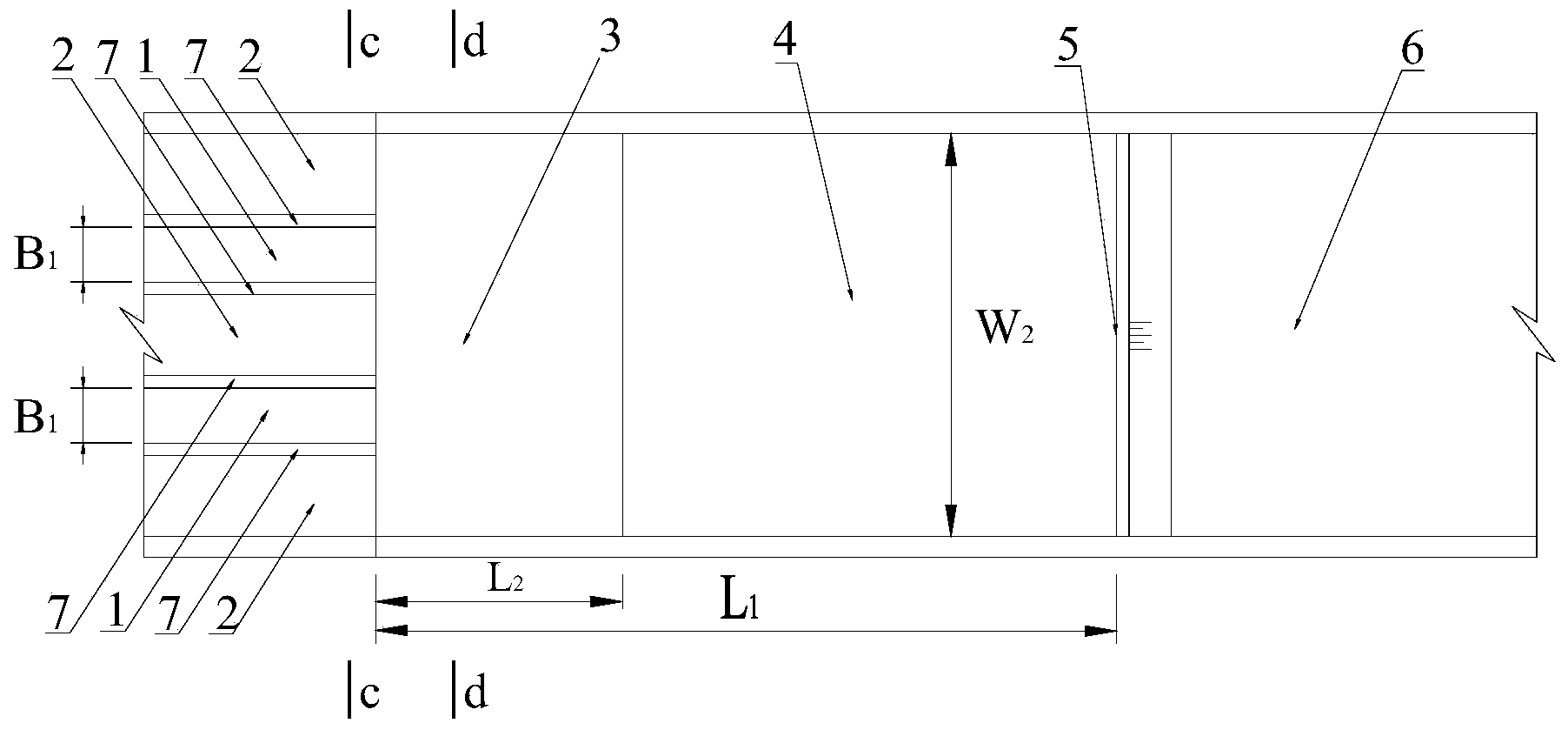
[0068] The structure of the high and low ridge stilling pools of the double-layer dispersed energy dissipation described in the embodiment of the present invention 3 is as follows figure 2 , image 3 , Figure 4 , Image 6 , Figure 8 As shown, it includes the water flow inlet section of the falling sill, the upper stilling basin 3 connected to the water flow inlet section, the lower stilling basin 4 behind the upper stilling basin 3, the tail sill 5 at the end of the stilling basin, and the stilling basin The connected apron 6 and the water flow inlet section are composed of low sill discharge holes 2 and high sill discharge holes 1 arranged alternately and a middle partition wall 7 between the low sill discharge holes and the high sill discharge holes.
[0069] figure 2 Displays the hole number N of the high sill discharge hole 1 1 is 2, the number of holes N of the low sill discharge hole 2 2 Be 3; On the basis that the holes on both sides are all low sill discharge...
PUM
| Property | Measurement | Unit |
|---|---|---|
| Length | aaaaa | aaaaa |
| Overall length | aaaaa | aaaaa |
Abstract
Description
Claims
Application Information
 - R&D
- Intellectual Property
- Life Sciences
- Materials
- Tech Scout
- Unparalleled Data Quality
- Higher Quality Content
- 60% Fewer Hallucinations
Browse by: Latest US Patents, China's latest patents, Technical Efficacy Thesaurus, Application Domain, Technology Topic, Popular Technical Reports.
© 2025 PatSnap. All rights reserved.Legal|Privacy policy|Modern Slavery Act Transparency Statement|Sitemap|About US| Contact US: help@patsnap.com