Split plunger device for non-shut-in continuous production

A split-type, plunger technology, which is used in the production of fluids, wellbore/well components, and earth-moving drilling, etc., can solve the problems of short plunger stroke, damage to the wellhead blowout preventer, and reduce the production efficiency of gas wells. The effect of bottom effusion, improving production efficiency and increasing gas production

Active Publication Date: 2014-03-26
PETROCHINA CO LTD
View PDF7 Cites 18 Cited by
  • Summary
  • Abstract
  • Description
  • Claims
  • Application Information

AI Technical Summary

Problems solved by technology

A longer shut-in time will not only affect the production of the gas well, but also drive the liquid in the gas well into the formation, reducing the production efficiency of the gas well
In addition, sometimes the upward stroke of the plunger is too short to reach the wellhead, and sometimes the upward impact force is too large, causing the wellhead blowout preventer to be damaged

Method used


Image

  • Split plunger device for non-shut-in continuous production
  • Split plunger device for non-shut-in continuous production
  • Split plunger device for non-shut-in continuous production

Examples


Embodiment

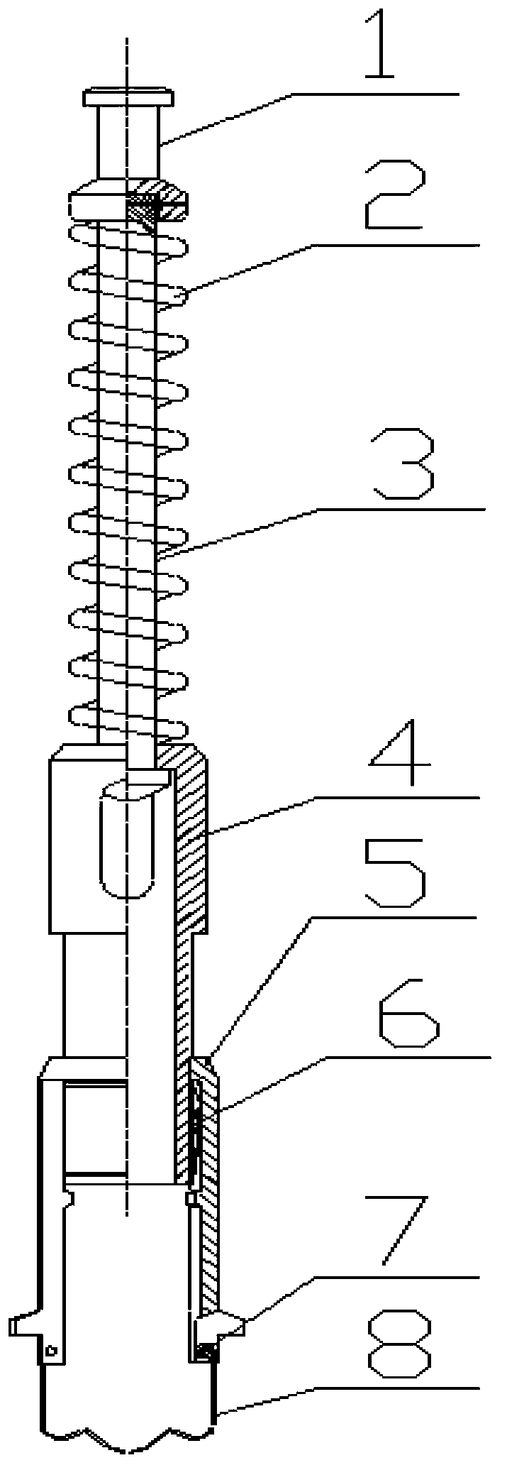
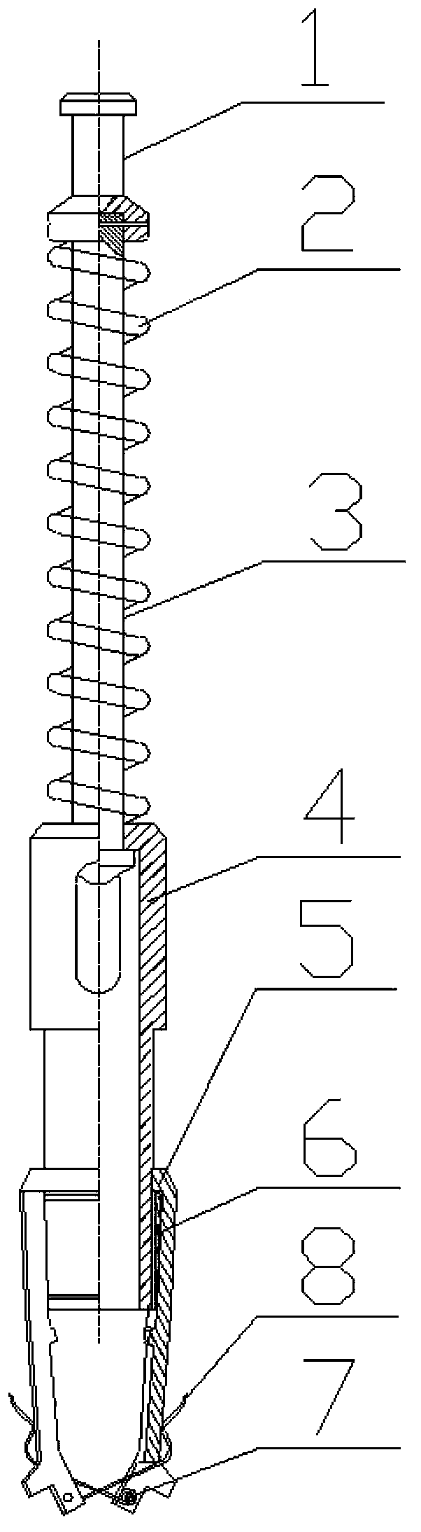
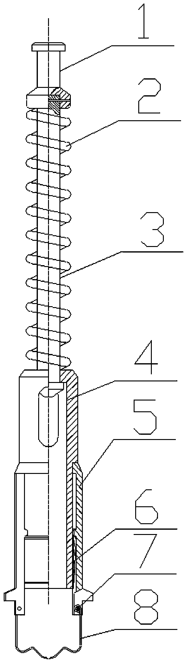
[0019] The split plunger device for continuous production without shutting down the well includes three parts: downhole buffer device, split plunger and wellhead buffer device:

[0020] The downhole buffer device is composed of a fishing head 1, a buffer spring 2, a connecting shaft 3, a guide tube 4, a seat seat 5, a locking sleeve 6, a steel wire clamp spring 7 and a pin shaft 8; the fishing head 1 is threadedly connected " T”-shaped connecting shaft 3, buffer spring 2 and guide tube 4 are set on the connecting shaft 3 in sequence, two oval through holes are symmetrically arranged on the wall of the upper part of the guide tube 4, and the bottom end of the guide tube 4 is threaded. The tapered locking sleeve 6, the outside of the locking sleeve 6 is the seat 5 on the lower diameter reducing tube of the sleeve guide tube 4; the inner wall of the seat 5 is provided with a shoulder, and the outer wall is symmetrically provided with slip wing grooves, Steel wire jumper 8 is conn...


PUM


Abstract

The invention discloses a split plunger device for non-shut-in continuous production and aims to achieve periodic liquid lifting using self-energy of a gas well and increase productivity. The split plunger device is composed of an underground buffer device, a split plunger and a wellhead buffer device. Specifically, the split plunger device comprises a buffer spring, a guide tube, a seating device, the split plunger, tapered seal rubber tubes, a seal tube, a fishing head, a slip, a drop bar and the like, wherein a connecting shaft is sleeved with the buffer spring and the guide tube, the guide tube is sleeved with the seating device which is connected with a wire circlip, the fishing head and the slip are connected with a body, and the drop bar is connected with a body connecting bar. The plunger of the split plunger device lifts liquid to a wellhead, splits up after being impacted by the wellhead buffer device, falls back to a down hole to seal again; under the condition of non-shut-in continuous production, the plunger device moves to and fro to periodically lift the liquid inside an oil tube by the aid of self-energy of the gas well. The split plunger device has the advantages that productivity can be improved, the shut-in limitation of the conventional plunger production is broken through, bottom hole accumulating liquid is discharged, and gas yield of the gas well is increased.

Description

technical field [0001] The invention relates to a split plunger device for continuous production without shutting down the well, and belongs to the technical field of drainage and gas recovery in oil and gas fields. Background technique [0002] With the continuous development of the Sulige Gas Field, some gas wells have entered the middle and late stage of low pressure and low production. The single well production is low and the liquid carrying capacity is poor. back pressure, and limit the production capacity of the wellbore, and finally the gas zone is completely crushed and the well is shut down, causing huge economic losses. Drainage gas recovery is an effective method to solve "gas well liquid accumulation", and it is also one of the important measures to tap the production potential of water-producing gas wells and improve the recovery rate. Plunger gas lift is one of the important measures to solve the liquid slippage of gas wells with low pressure, low production ...

Claims


Application Information

Patent Timeline
Patent Type & Authority Applications(China)
IPC IPC(8): E21B43/00
Inventor 肖述琴张书平徐勇陈德见于志刚卫亚明杨旭东程小莉陈勇李耀德
Owner PETROCHINA CO LTD
Why Eureka
Try Eureka