Method and system for operating an engine turbocharger

A turbocharger, engine technology, applied in engine components, combustion engines, engine control, etc., can solve problems such as increased system cost, unreliability, etc., to reduce the amount of time and reduce engine emissions.

Active Publication Date: 2014-03-26
FORD GLOBAL TECH LLC
View PDF3 Cites 7 Cited by
  • Summary
  • Abstract
  • Description
  • Claims
  • Application Information

AI Technical Summary

Problems solved by technology

But systems that inject air into the engine exhaust system add to system cost and may be less reliable than systems that do not inject air into the engine exhaust

Method used


Image

  • Method and system for operating an engine turbocharger
  • Method and system for operating an engine turbocharger
  • Method and system for operating an engine turbocharger

Examples


Embodiment Construction

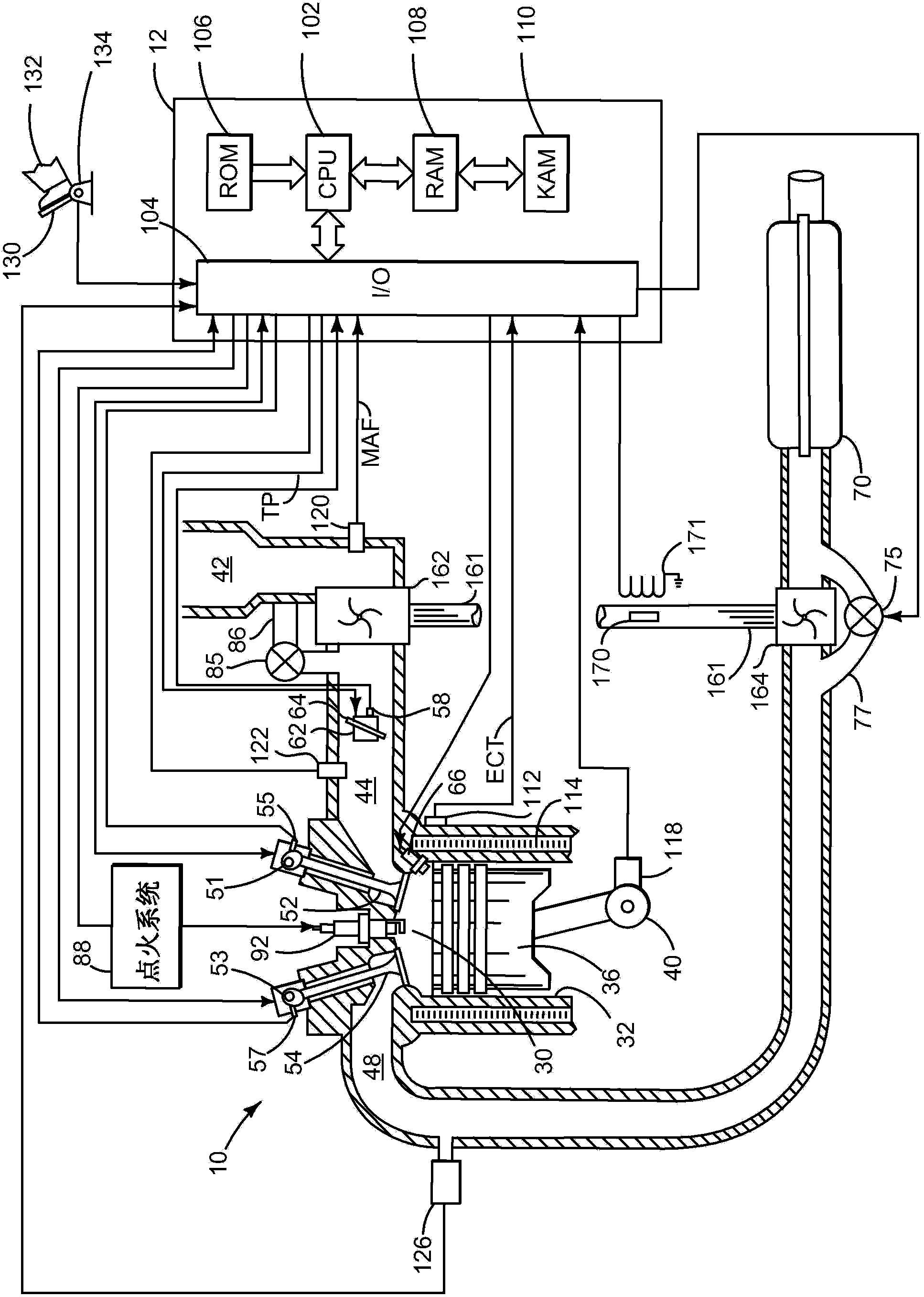
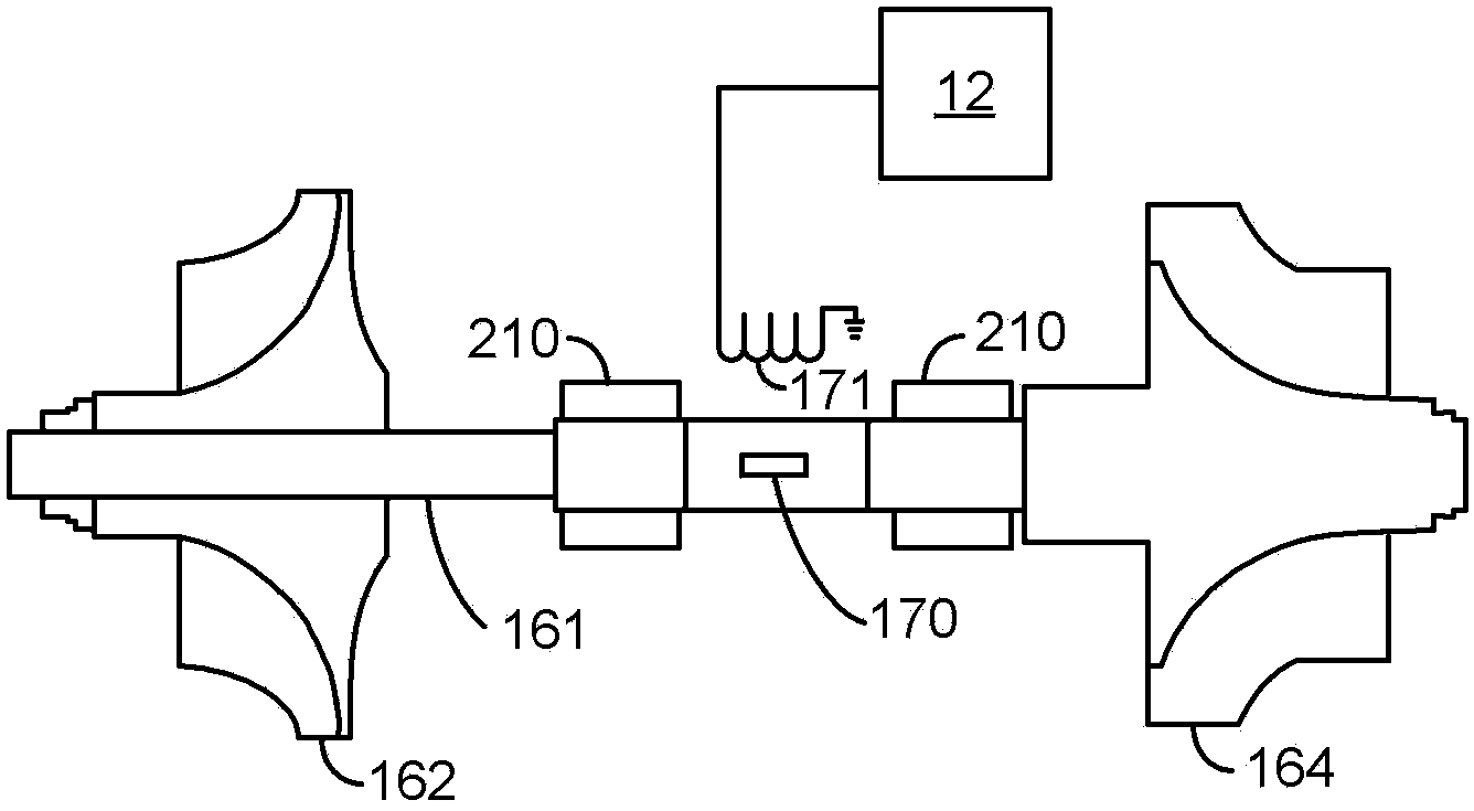
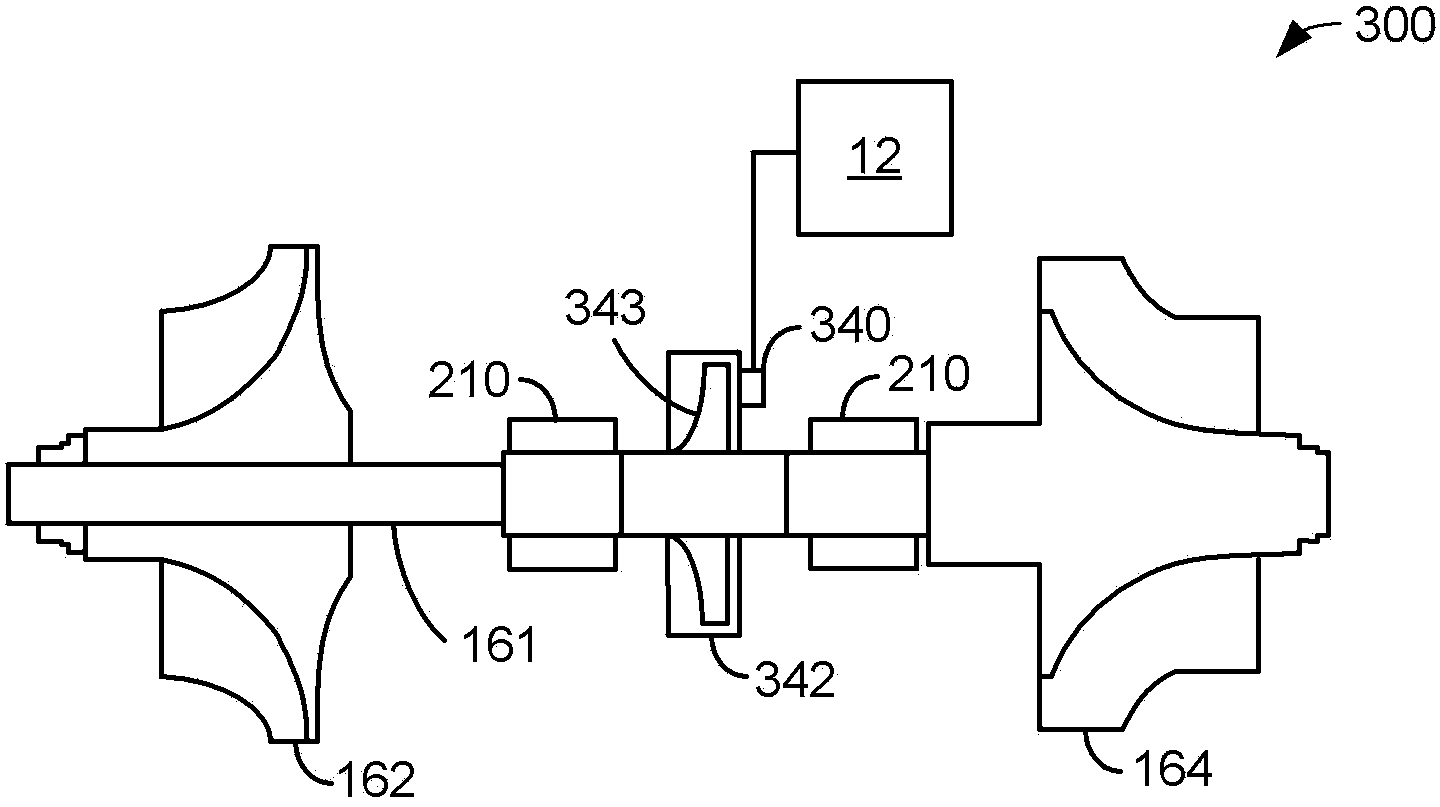
[0023] The invention relates to operating a turbocharger. In one example, a turbocharger turbine rotates in a direction determined by exhaust gas from cylinders of the engine. In another example, the turbocharger turbine rotates in a direction opposite to the direction the turbine rotates when driven by engine exhaust. This approach may improve engine emissions by improving oxidation of exhaust gas in the exhaust manifold. figure 1 An exemplary system is shown. Can use Figure 8 The method shown operates the engine and turbocharger to provide Figure 6 and Figure 7 the sequence of. figure 2 and image 3 An exemplary turbocharger is shown in . Figure 4 and Figure 5 show the basis Figure 8 approach to exhaust flow near the turbocharger. Figure 6 and Figure 7 shown in the Figure 8 approach to the engine start sequence.

[0024] refer to figure 1 , an internal combustion engine 10 comprising a plurality of cylinders is controlled by an electronic engine contr...


PUM


Abstract

A system and method for operating an engine turbocharger is described. In one example, the turbocharger is rotated in different directions in response to operating conditions. The system and method may reduce engine emissions.

Description

Background technique [0001] It may be desirable to reduce engine emissions when starting the engine so that average engine emissions over the drive cycle may be reduced. One way to improve engine emissions at start-up is to run the engine under rich conditions and supply air to an exhaust system coupled to the engine. Such operation enables engine exhaust components to be oxidized in the exhaust system. In particular, hydrocarbons in the exhaust gas can be oxidized when combined with air introduced into the exhaust system. The oxidized hydrocarbons release heat, which can be transferred to aftertreatment devices in the exhaust system. Heat transfer reduces the amount of time required for the aftertreatment device to reach operating temperature. As a result, the aftertreatment device may begin converting exhaust components to more desirable compounds sooner after engine start, thereby reducing engine emissions. But systems that inject air into the engine exhaust add to syst...

Claims


Application Information

Patent Timeline
Patent Type & Authority Applications(China)
IPC IPC(8): F02B37/12
CPCF01N3/2006F02B37/10F02B39/08F02B39/10F02D23/00F02D41/0007F02D41/061F02D41/062F02D2200/0802Y02T10/12Y10S903/905F02B37/183F02B37/225
Inventor W·C·罗那K·D·伯德K·M·普拉根斯
Owner FORD GLOBAL TECH LLC
Why Eureka
Try Eureka