Stainless steel cable tie
A stainless steel and belt feeding technology, which is applied to pipeline supports, connecting components, electrical components, etc., can solve the problems of small friction coefficient of belt body and accidents, and achieve the effect of average friction force, uniform force, and increase of friction force.
- Summary
- Abstract
- Description
- Claims
- Application Information
AI Technical Summary
Problems solved by technology
Method used
Image
Examples
Embodiment 1
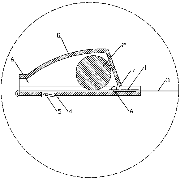
[0031] The stainless steel cable tie of the present invention is as figure 1 As shown, it includes a locking mechanism 8 and a cable tie strip 3, the locking mechanism 8 and the cable tie strip 3 are all made of stainless steel, and the two ends of the locking mechanism 8 are respectively provided with mutually connected belt inlets 6 And the belt outlet 7, a steel ball raceway is formed between the belt inlet 6 and the belt outlet 7 and steel balls 2 are arranged in the steel ball raceway, the height of the steel ball raceway is from the belt inlet The mouth 6 increases toward the tape outlet 7 and shrinks at the tape outlet 7. One end of the cable tie strip 3 is fixed at the tape inlet 6, and the other end is a free end extending from the tape outlet 7. The free end of the belt 3 is inserted into the locking mechanism 8 from the belt inlet 6, and after insertion, the steel ball 2 is pushed to move toward the belt outlet 7. When the steel ball 2 moves to the highest posi...
Embodiment 2
[0034] On the basis of the stainless steel cable tie described in Example 1, the friction barbs 1 on the cable tie strip 3 are preferably evenly distributed on the inner and outer surfaces of the cable tie strip 3, and the cable tie strip 3 is also compatible with the cable tie The inner wall of the locking mechanism 8 is contacted and connected, so the friction barbs 1 are set on both sides to increase the friction to a greater extent, reduce the sliding of the cable tie strip 3, and evenly distribute the friction to make it more uniform. Stability is better.
[0035] The cable tie strip 3 is bent at the belt inlet 6 and is attached to the inner wall and the outer wall of the locking mechanism 8, as figure 1As shown, a notch 4 is provided on the outer wall of the locking mechanism 8, and a protrusion 5 is provided on the cable tie strip 3, and the protrusion 5 extends into the notch 4, and the notch 4 The length of the opening 4 is preferably longer than the protrusion 5. Wh...
Embodiment 3
[0037] On the basis of the stainless steel cable ties described in the above embodiments, the friction barb 1 on the inner wall of the locking mechanism 8 is set at a position close to the belt inlet 6, close to the belt outlet 7 or both positions, which can be set according to the actual situation. Need, set the position of the friction barb 1 on the inner wall of the locking mechanism 8, if the bundled article is light, one place can be arranged, if the bundled article is heavy, two places can be arranged, so that the scope of application of this product is wider.
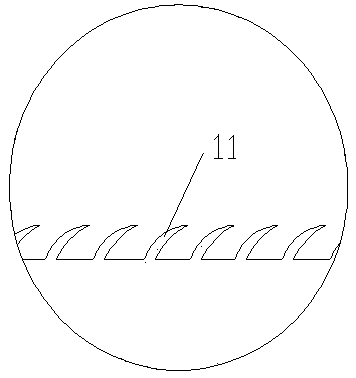
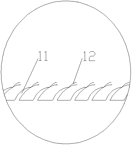
[0038] The friction barb 1 is a sharp thorn-like protrusion 11 inclined toward the tape outlet 7, and the thorn-like protrusion is evenly distributed, such as figure 2 As shown, this structure has very little resistance when the cable tie strip 3 inserted into the locking mechanism 8 moves toward the belt outlet 7, so that it can be easily inserted, and the frictional resistance when the cable tie strip 3 moves t...
PUM
 Abstract
Description
Claims
Application Information
 - R&D
- Intellectual Property
- Life Sciences
- Materials
- Tech Scout
- Unparalleled Data Quality
- Higher Quality Content
- 60% Fewer Hallucinations
Browse by: Latest US Patents, China's latest patents, Technical Efficacy Thesaurus, Application Domain, Technology Topic, Popular Technical Reports.
© 2025 PatSnap. All rights reserved.Legal|Privacy policy|Modern Slavery Act Transparency Statement|Sitemap|About US| Contact US: help@patsnap.com


