
Inbuilt damping device for hollow shaft

A technology of vibration damping device and hollow shaft, which is applied in the direction of spring/shock absorber, vibration suppression adjustment, rotation vibration suppression, etc., can solve the problem of occupying external space, and achieve space-saving, cost-saving, and obvious effects of vibration reduction

Active Publication Date: 2014-03-26
JIANGSU UNIV OF SCI & TECH
View PDF6 Cites 14 Cited by
  • Summary
  • Abstract
  • Description
  • Claims
  • Application Information

AI Technical Summary

Problems solved by technology

Dynamic vibration absorbers have been widely used in various fields, but they are not introduced into the vibration of the hollow shaft system, and various types of vibration absorbers are mostly outside the shaft, occupying the external space

Method used


Image

  • Inbuilt damping device for hollow shaft
  • Inbuilt damping device for hollow shaft
  • Inbuilt damping device for hollow shaft

Examples


Embodiment Construction

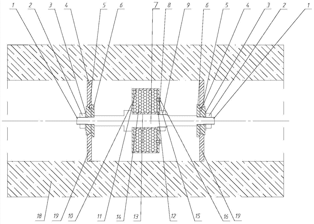
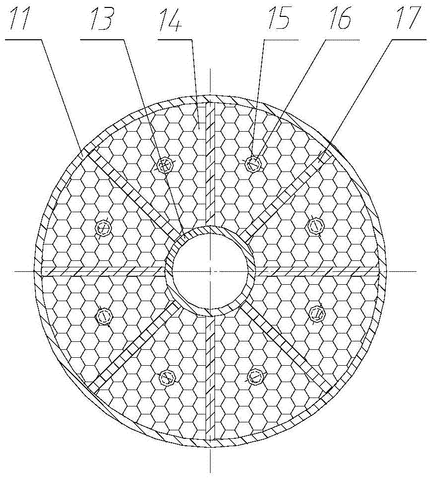
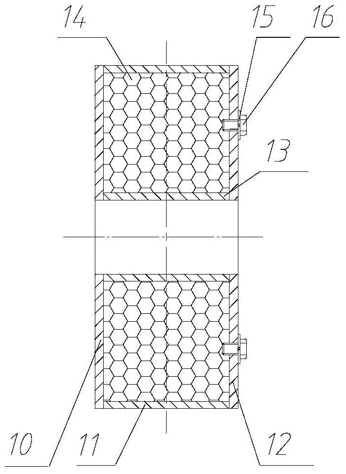
[0030] like figure 1 , 2 , 3, 4, 5, and 7, a hollow shaft built-in vibration damping device includes an elastic shaft 1 placed in the hollow shaft, and the elastic shaft 1 is a three-stage stepped shaft structure, wherein one end of the middle section is along the The axes are three diameters of large, medium and small in turn, and the two ends and one section are respectively from the end faces of the two ends of the middle section and are smaller than the small diameter of the middle section along the axis to the respective ends. The sections are all provided with threads; the middle diameter of the middle section is covered with a cylindrical inertial wheel 7 filled with damping particles 14 and a gasket 2 8, and the cylindrical inertial wheel 7 is fastened by connecting the nut 29 with the thread, The middle diameters of the two ends are respectively fitted with stoppers 6, pushers 5 and spacers 3, wherein the pushers 5 are truncated conical bodies with a central hole, an...


PUM


Abstract

An inbuilt damping device for a hollow shaft comprises an elastic shaft arranged in the hollow shaft. The elastic shaft is of a three-segmental stepped shaft structure. One end of the middle segment is sequentially divided into a large diameter, a medium diameter and a small diameter along the axial line; the segments at the two ends are respectively divided into large diameters, medium diameters and small diameters in sequence along the axial line in the direction from the two end faces of the middle segment to the respective ends in the mode of being smaller than the small diameter of the middle segment; the segments of the small diameters of the three segments of stepped shafts are all provided with threads; a cylindrical inertia wheel and a second spacer are installed on the medium diameter of the middle segment in a sleeved mode, and the cylindrical inertia wheel is filled with damping particles and is fastened by connecting a second nut and the threads; the medium diameters of the segments at the two ends are respectively sleeved with a stop block, a taper and a first spacer, wherein the tapers are circular-frustum-shaped bodies provided with center holes; upper membranes and lower membranes are installed on the outer conical surfaces of the tapers in a sleeved mode and provided with taper holes; the tapers are fastened by connecting first nuts and the threads. According to the inbuilt damping device for the hollow shaft, torsional vibration, transverse vibration, longitudinal vibration and coupling vibration on a shafting can be simultaneously controlled; furthermore, the inbuilt damping device has the damping effect of more than 10dB on broadband excitation force within a wide rotating speed range of the shafting.

Description

technical field [0001] The invention belongs to the technical field of dynamic vibration absorbers and damping vibration reduction, and relates to a built-in vibration reduction device of a hollow shaft, and more particularly relates to a vibration reduction device for torsional vibration, transverse vibration, longitudinal vibration and coupling vibration of a hollow shaft. Background technique [0002] In order to meet the mobility, flexibility requirements and size constraints, some special ships such as tugboats and ocean engineering ships use medium and high-speed diesel engines, thus adopting high-speed shafting. In high-speed shafting, the hollow shaft is light in weight and relatively stable in performance, and can be widely used. [0003] There are three types of vibration of the hollow shaft system during operation: lateral vibration caused by unbalanced rotating shaft, which can be vertical or horizontal, which will cause the bearing seat to loosen or even rupture...

Claims


Application Information

Patent Timeline
Patent Type & Authority Applications(China)
IPC IPC(8): F16F15/12F16F15/121F16F15/22
Inventor 温华兵刘林波沈那伟昝浩
Owner JIANGSU UNIV OF SCI & TECH
Learn More