A planetary reducer

A technology of planetary reducer and reducer, which is applied in the direction of transmission parts, gear transmission, belt/chain/gear, etc., can solve the development trend that does not meet the miniaturization of equipment, cannot install small equipment, and enlarge the reducer Volume and other issues, to achieve the effect of reducing size, volume and weight, and reducing load strength

Active Publication Date: 2016-05-04
CHONGQING CHUANYI AUTOMATION
View PDF6 Cites 0 Cited by
  • Summary
  • Abstract
  • Description
  • Claims
  • Application Information

AI Technical Summary

Problems solved by technology

[0003] However, when the transmitted power is large, it is necessary to increase the size of each part of the reducer to increase the load strength of the reducer. In this way, the volume of the reducer will inevitably increase, and it cannot be installed in small equipment, which does not meet current requirements. Development trend of equipment miniaturization

Method used


Image

  • A planetary reducer
  • A planetary reducer
  • A planetary reducer

Examples


Embodiment Construction

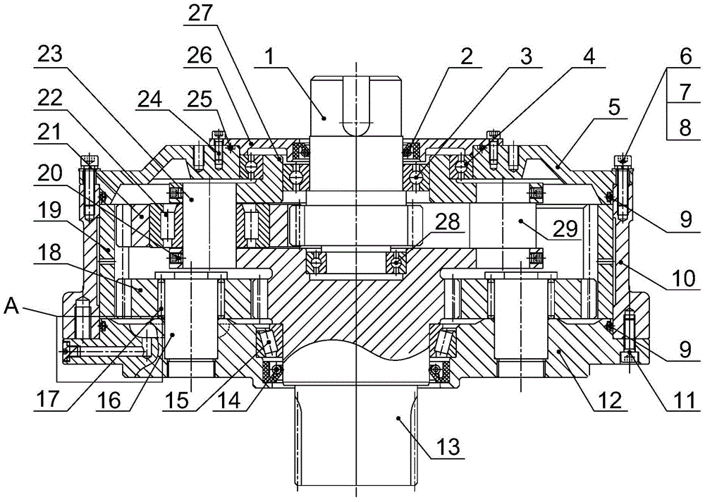
[0029] The core of the present invention is to provide a planetary reducer, which reduces the volume of the planetary reducer under the same power condition.

[0030] The following will clearly and completely describe the technical solutions in the embodiments of the present invention with reference to the accompanying drawings in the embodiments of the present invention. Obviously, the described embodiments are only part of the embodiments of the present invention, not all of them. Based on the embodiments of the present invention, all other embodiments obtained by persons of ordinary skill in the art without making creative efforts fall within the protection scope of the present invention.

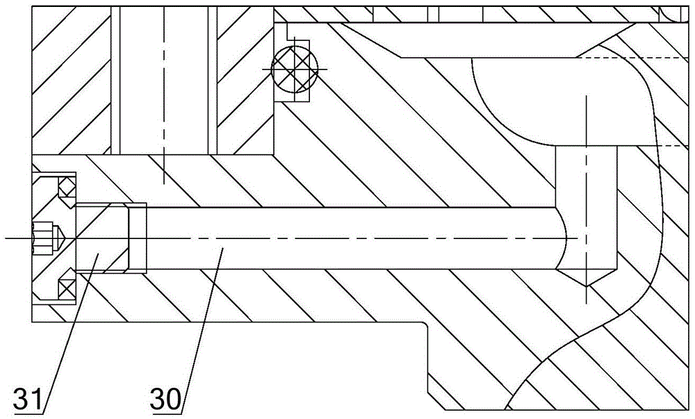
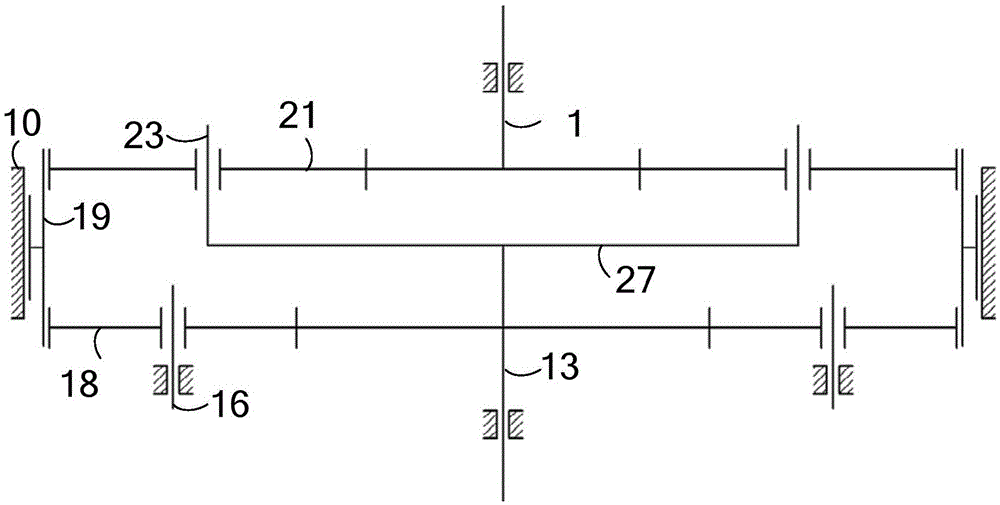
[0031] Please refer to figure 1 with figure 2 , figure 1 A schematic structural diagram of a planetary reducer provided for an embodiment of the invention; figure 2 for figure 1 Partial enlarged view of part A in ; image 3 It is a schematic transmission diagram of a planetary red...


PUM


Abstract

The invention discloses a planetary speed reducer. The planetary speed reducer comprises a speed reducer box shell, an input shaft, an output shaft, an input gear, a planetary frame end plate, a plurality of planetary wheel axles, a planetary wheel, an annular gear, a plurality of idle wheels and an idle wheel axle, wherein the input gear is arranged on the input shaft, the planetary frame end plate is rotatably installed on the speed reducer box shell, the planetary wheel axles are fixedly connected with the planetary frame end plate and the output shaft, the planetary wheel is rotatably connected to the planetary wheel axles and is meshed with the input gear, the annular gear is meshed with the planetary wheel, the annular gear is rotatably connected into the speed reducer box shell, the idle wheels are meshed with the annular gear and the output gear of the output shaft, and the idle wheel axle is rotatably connected with the idle wheels and fixed inside the speed reducer box shell. The transmission method of power dividing is adopted in the planetary speed reducer, the power is divided into two paths, the power in one path is transmitted to the output shaft through the input shaft, the planetary wheel, the planetary wheel axle, and the power in the other path is transmitted to the output shaft through the input shaft, the planetary wheel, the annular gear and the idle wheel. Accordingly, the load of the signal part is reduced, and the size of the planetary speed reducer is reduced under the same power condition.

Description

technical field [0001] The invention relates to the technical field of reducers, in particular to a planetary reducer. Background technique [0002] The principle of a planetary reducer is to use a planetary gear mechanism to achieve deceleration. The planetary gear mechanism usually includes a sun gear, a planetary gear, a planetary carrier and a ring gear. The planetary gear is supported by the planetary carrier and revolves around the sun gear. The planetary gear mechanism of the existing planetary reducer uses the sun gear as the active part, and the planet carrier as the passive part, so as to realize power transmission. [0003] However, when the transmitted power is large, it is necessary to increase the size of each part of the reducer to increase the load strength of the reducer. In this way, the volume of the reducer will inevitably increase, and it cannot be installed in small equipment, which does not meet current requirements. The development trend of equipment...

Claims


Application Information

Patent Timeline
Patent Type & Authority Patents(China)
IPC IPC(8): F16H1/28F16H57/023F16H57/029F16H57/031F16H57/08
CPCF16H1/28F16H57/023F16H57/029F16H57/031F16H57/08F16H2057/02086
Inventor 李巧游军
Owner CHONGQING CHUANYI AUTOMATION
Why Eureka
Try Eureka