Supercharge Your Innovation With Domain-Expert AI Agents!

Gear mechanism for balance shaft of engine

A technology of gear mechanism and balance shaft, applied in belts/chains/gears, mechanical equipment, components with teeth, etc., can solve the problems of inability to drive, loss of buffer, manpower, material resource consumption, etc., to extend service life, eliminate backlash effect

Inactive Publication Date: 2014-03-26
KYMCO
View PDF6 Cites 4 Cited by
  • Summary
  • Abstract
  • Description
  • Claims
  • Application Information

AI Technical Summary

Problems solved by technology

[0005] However, the inside of the engine 1 is full of engine oil and is often in a high-temperature environment, so that the rubber blocks 224 are easy to rapidly deteriorate and harden, causing the rubber blocks 224 to be easily sheared when the outer ring portion 221 and the inner ring portion 222 rotate relatively. The force effect is destroyed, and the buffering function is lost, and only the springs 225 are left to provide the buffering effect, but after a long time of use, the springs 225 will still be cut off so that the outer ring part 221 cannot drive the inner ring part 222, resulting in The shaft 21 of the balance shaft unit 2 cannot be driven to rotate, and it may even cause a serious accident of damage to the engine 1. Therefore, it is necessary to replace the rubber blocks 224 regularly, resulting in the consumption of manpower and material resources.

Method used


Image

  • Gear mechanism for balance shaft of engine
  • Gear mechanism for balance shaft of engine
  • Gear mechanism for balance shaft of engine

Examples


Embodiment Construction

[0016] The aforementioned and other technical contents, features and effects of the present invention will be clearly presented in the following detailed description of a preferred embodiment with reference to the accompanying drawings.

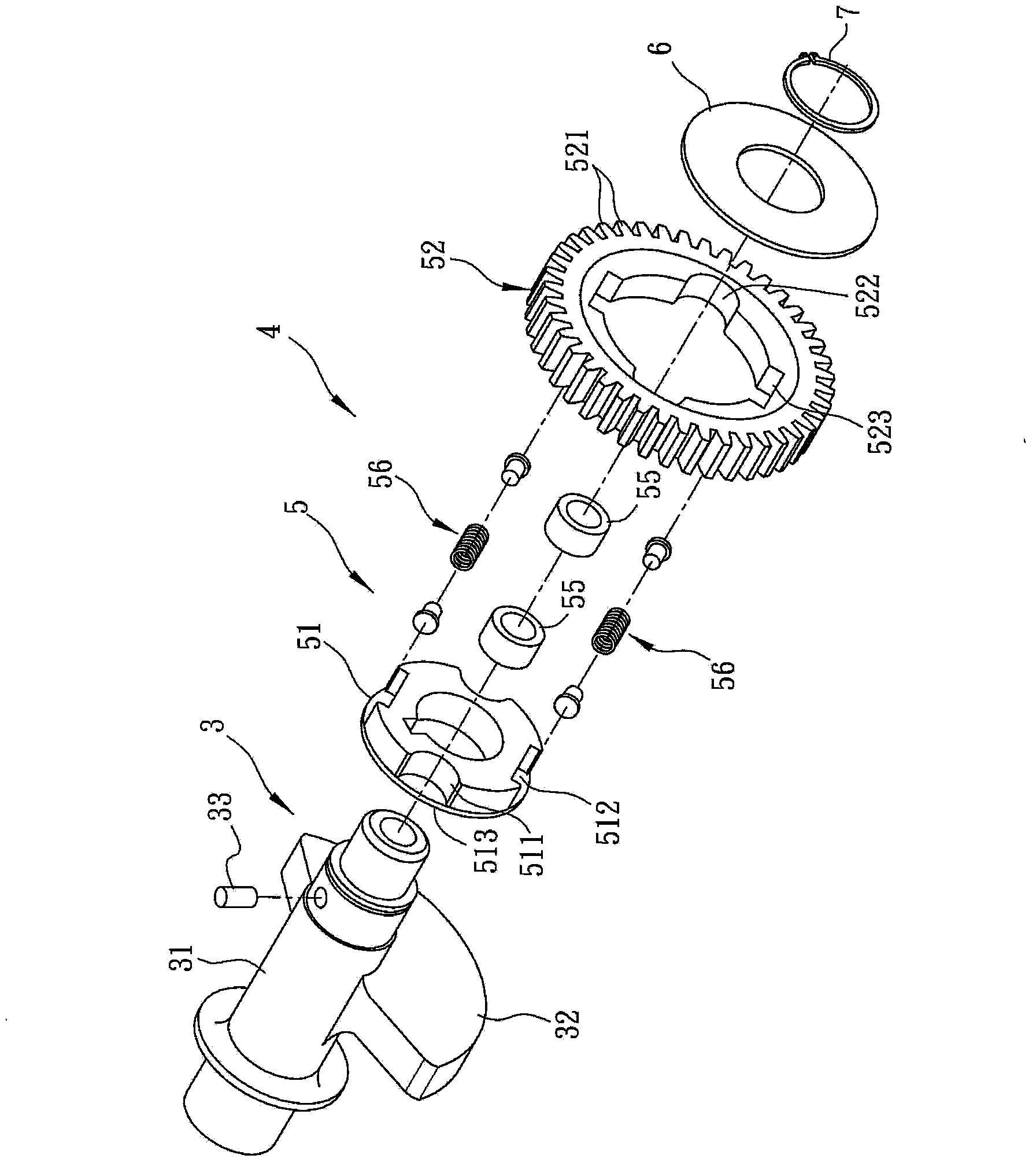
[0017] refer to image 3 and Figure 4 , which is a preferred embodiment of the gear mechanism 4 used for the balance shaft of the engine according to the present invention, the balance shaft 3 includes a shaft 31 and a counterweight 32 located on the shaft 31 . The gear mechanism 4 includes a driven gear set 5 set on the shaft 31, a fixed plate 6 covering the side of the driven gear set 5 opposite to the counterweight 32 and passing through the shaft 31, And a buckle 7 buckled on the shaft 31 and engaged with the fixing piece 6 . In this embodiment, the buckle 7 is a C-shaped buckle, but it is not limited thereto.

[0018] The driven gear set 5 includes an inner ring 51 fixed on the shaft 31 , an outer ring 52 surrounding the inner ring 5...


PUM


Abstract

The invention discloses a gear mechanism for a balance shaft of an engine. The gear mechanism for the balance shaft of the engine comprises a driven gear set, wherein the driven gear set comprises an inner ring piece, an outer ring piece and multiple first elastic elements, the inner ring piece is fixed to a shaft rod of the balance shaft in a sleeved mode, the inner ring piece is surrounded by the outer ring piece, the first elastic elements are arranged between the inner ring piece and the outer ring piece in an embedded mode, each first elastic element is provided with a buffer portion and a core portion, the buffer portions are connected with the inner ring piece and the outer ring piece and are made of flexible materials, the core portions are arranged in the buffer portions, the rigidity of the core portions is higher than the rigidity of the buffer portions, and the outer ring piece is provided with multiple convex teeth which are used for being meshed with a driving gear. According to the gear mechanism for the balance shaft of the engine, due to the fact that a buffering effect and a restoring effect can be achieved through the buffer portions of the first elastic elements, back clearance between each two adjacent teeth can be eliminated; due to the fact that the rigidity of the core portions is high, the first elastic elements are prevented from being damaged by shearing force, and the service life of the first elastic elements is prolonged.

Description

technical field [0001] The present invention relates to a gear mechanism, in particular to a gear mechanism for a balance shaft of an engine. Background technique [0002] refer to figure 1 and figure 2 , is an existing engine 1, the engine 1 has a crankcase 11, a crankshaft 12 pivotally connected in the crankcase 11, and a crankshaft 12 pivotally connected in the crankcase 11 and linked with the crankshaft 12 Balance shaft unit 2. The crankshaft 12 has at least one flywheel part 121 for increasing inertia, and a driving gear part 122 . The balance shaft unit 2 has a shaft 21 pivotally connected to the crankcase 11, a driven gear 22 fixed on the shaft 21 and meshed with the driving gear part 122 of the crankshaft 12, and a The shaft 21 is extended by a counterweight 23 . The driven gear 22 has an outer ring part 221 formed with a plurality of protruding teeth, an inner ring part 222 rotatably arranged in the outer ring part 221 and fixedly connected with the shaft rod ...

Claims


Application Information

Patent Timeline
Patent Type & Authority Applications(China)
IPC IPC(8): F16H55/18F16H55/14
CPCF16H55/14F16H55/18
Inventor 郭伟信郑温坐苏泓瑜
Owner KYMCO
Features
  • R&D
  • Intellectual Property
  • Life Sciences
  • Materials
  • Tech Scout
  • Unparalleled Data Quality
  • Higher Quality Content
  • 60% Fewer Hallucinations
Learn More