Novel stop valve

A cut-off valve, a new type of technology, applied in the direction of valve details, safety valves, balance valves, etc., can solve the problems of complicated connection and debugging, high cost, and large overall shape and volume, and achieve low manufacturing cost, low cost, and pressure setting. flexible effect

Active Publication Date: 2014-03-26
WUZHONG INSTR
View PDF8 Cites 6 Cited by
  • Summary
  • Abstract
  • Description
  • Claims
  • Application Information

AI Technical Summary

Problems solved by technology

[0003] Obviously, the adoption of this solution has the disadvantages of complex product connection and debugging, large overall size and high cost.

Method used


Image

  • Novel stop valve
  • Novel stop valve
  • Novel stop valve

Examples


Embodiment Construction

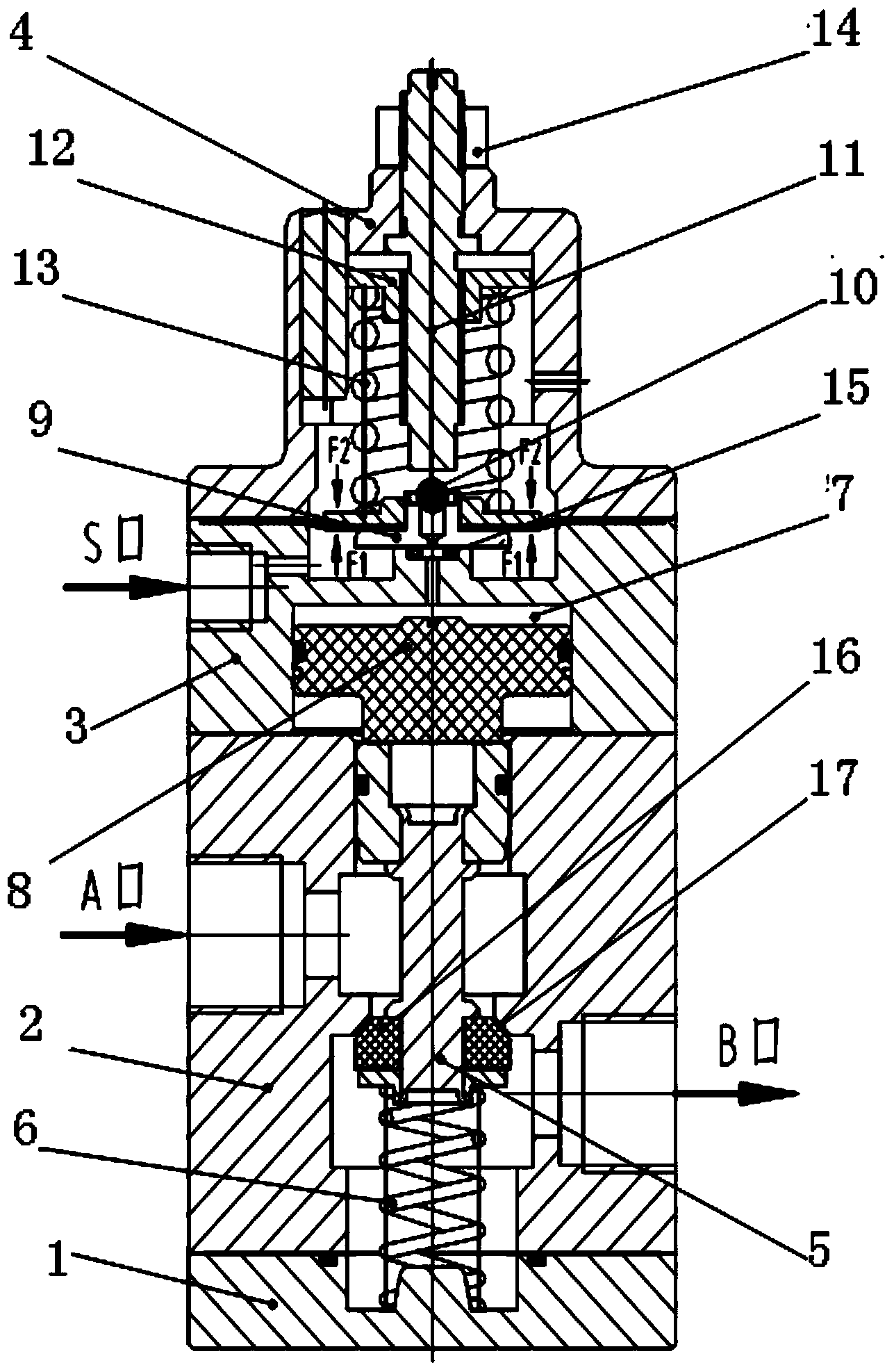
[0018] like figure 2 , 3 , 4, and 5, the present invention is a new cut-off valve, including a base 1, on which a reversing chamber 2, a piston chamber 3 and a pressure regulating chamber 4 are sequentially installed on the base 1, wherein the reversing chamber 2 are respectively opened with an inlet (namely A port) and an outlet (namely B port), a valve core part 5 is installed in the reversing chamber 2, the lower end of the valve core part 5 is connected with the base 1 through a return spring 6 and its The upper end is connected with the air control piston 8 installed in the air pressure chamber 7 in the piston chamber 3 .

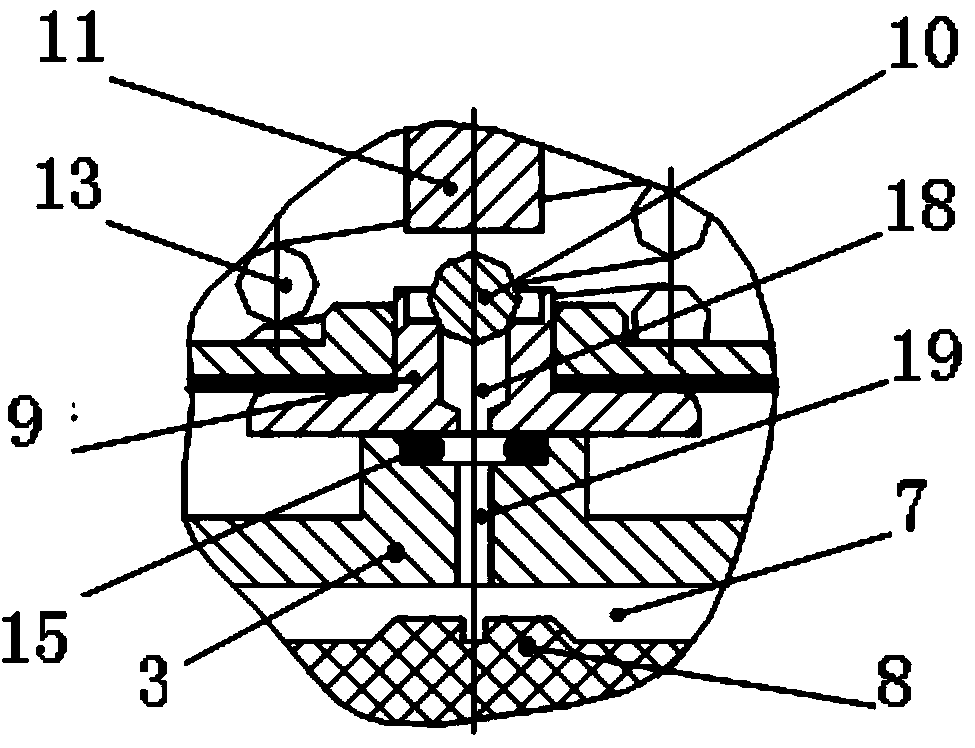
[0019] Wherein, a diaphragm tray part 9 is installed in the pressure regulating chamber 4, and an exhaust hole 18 is arranged in the middle of the diaphragm tray part 9. Cavity 7 communicates, and a steel ball 10 is installed on the upper end of the exhaust hole 18, and a detection air pressure port (namely S port) is also opened on the aforemention...


PUM


Abstract

The invention relates to a novel stop valve. The novel stop valve is characterized in that the novel stop valve comprises a base (1), a reversing cavity (2), a piston cavity (3) and a pressure regulating cavity (4) are sequentially installed on the base (1) from bottom to top, the reversing cavity (2) is provided with an inlet and an outlet, a valve element component (5) is installed in the reversing cavity (2), the lower end of the valve element component (5) is connected with the base (1) through a reset spring (6), the upper end of the valve element component (5) is connected with an air-controlled piston (8) installed in an air pressure cavity (7) in the piston cavity (3), a diaphragm tray component (9) is installed in the pressure regulating cavity (4), and an exhaust hole (18) is formed in the middle of the diaphragm tray component (9). The pilot-operated type operating principle is adopted in the novel stop valve, and the two-position two-way stop valve can detect air source pressure and achieve automatic reversing.

Description

technical field [0001] The invention relates to a novel cut-off valve. Background technique [0002] The traditional control scheme is as follows: when the pressure needs to be detected and the air circuit is cut off in the pneumatic control circuit, the combination of "pneumatic pressure switch" and "two-way cut-off valve" is used to realize it. like figure 1 As shown, the traditional control scheme is briefly described with the control case of the pneumatic control valve in the process control industry. The pressure reducing valve decompresses the air source and inputs it to the positioner, and the positioner controls the pneumatic actuator according to the input current signal of 4-20mA; when the pressure of the air source of the pressure reducing valve is lower than the set value of the air source failure , the control system requires the pneumatic actuator to remain at the position before the air source failed. The pneumatic pressure switch is used to detect the outp...

Claims


Application Information

Patent Timeline
Patent Type & Authority Applications(China)
IPC IPC(8): F16K17/06F16K31/124
CPCF16K17/06F16K31/1221F16K31/1225
Inventor 马玉山高强余少华
Owner WUZHONG INSTR
Why Eureka
Try Eureka