Light source device

A light source device and light source technology, applied in light sources, electric light sources, lighting devices, etc., can solve the problems of substrate size reduction restrictions, locking tools scratching light bars, and inability to connect in a straight line, etc., to reduce the overall structure thickness and small size Effect

Inactive Publication Date: 2016-06-01
CORETRONIC
View PDF13 Cites 0 Cited by
  • Summary
  • Abstract
  • Description
  • Claims
  • Application Information

AI Technical Summary

Problems solved by technology

However, when using screws to lock the substrate, it is usually locked from the inside of the backplane, which is likely to cause interference between the locking tool (such as a screwdriver) and the backplane, resulting in inaccurate locking and affecting assembly efficiency, and even causing lock. Attached tool slides and scratches the light bar
In addition, if the substrate is fixed by locking, a locking hole must be provided on the substrate, and the circuit on the substrate must bypass the locking hole and cannot be connected in a straight line, which will not only make the circuit layout on the substrate more complicated, but also make the substrate size The shrinkage is limited and cannot meet the thinning needs of electronic products

Method used


Image

  • Light source device
  • Light source device
  • Light source device

Examples


Embodiment Construction

[0073] The foregoing and other technical contents, features and effects of the present invention will be clearly presented in the following detailed description of multiple embodiments with reference to the accompanying drawings. The directional terms mentioned in the following embodiments, such as up, down, front, back, left, right, etc., are only directions referring to the drawings. Accordingly, the directional terms are used to illustrate, not to limit, the invention.

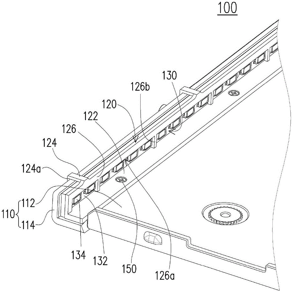
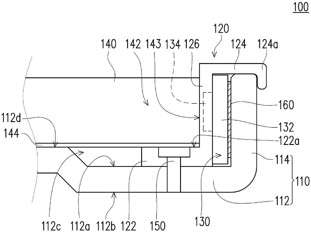
[0074] figure 1 It is a partial perspective view of a light source device according to an embodiment of the present invention. figure 2 for figure 1 Partial cross-sectional view of the light source device. In order to make the drawings more clear, figure 1 not shown figure 2 The light guide plate 140 in. Please refer to figure 1 and figure 2 , the light source device 100 of this embodiment is, for example, a backlight module applied to an electronic device. The light source device 100 includes a...


PUM


Abstract

Provided is a light source device. The light source device comprises a back plate, a fixing part and a light source. The back plate comprises a base plate and a side wall, and an included angle is formed between the base plate and the side wall. The fixing part comprises a first assembly portion, a second assembly portion and a fixing portion, the first assembly portion is parallel to the base plate, and the fixing portion is connected with the first assembly portion and the second assembly portion. The first assembly portion is fixed to the base plate, and the second assembly portion is fixed to the side wall. The light source is clamped between the side wall and the fixing portion. The light source device can improve the assembly efficiency and lower overall structure thickness.

Description

technical field [0001] The invention relates to a light source device. Background technique [0002] In recent years, the technology industry has become increasingly developed, digital tools such as optical scanners (optical scanners), mobile phones (mobile phones), digital cameras (digital cameras) and notebook computers (notebooks) and other electronic products have become more and more popular, and are moving towards convenience, multi- Functional and beautiful design direction for development. As users' demands on electronic products are increasing day by day, backlight modules in electronic products have also become the focus of design improvement. [0003] The backlight module, for example, uses a light bar (light bar) composed of light emitting diodes (light emitting diodes, LEDs) and a substrate (such as a circuit board) as a light source. In the prior art, the substrate is generally locked to the backplane of the backlight module by screws. However, when using sc...

Claims


Application Information

Patent Timeline
Patent Type & Authority Patents(China)
IPC IPC(8): F21S8/00F21V19/00F21V17/10F21Y115/10
Inventor 尤嘉宏袁明浩
Owner CORETRONIC
Why Eureka
Try Eureka