Mounting structure of a lamp assembly

A technology for installation structures and lamps, which is applied in cooling/heating devices of lighting devices, lighting devices, lighting auxiliary devices, etc. It can solve the problems of environmental temperature installation breakage, overall weight increase, and unsightly appearance, and achieve a high degree of overall combination stability , simplified assembly, beautiful appearance

Inactive Publication Date: 2014-03-26
TAIWAN FU HSING INDAL
View PDF4 Cites 2 Cited by
  • Summary
  • Abstract
  • Description
  • Claims
  • Application Information

AI Technical Summary

Problems solved by technology

[0003] Moreover, even with the case image 3 The hook is designed to allow the colored light-transmitting cover to be combined with the lampshade, but because of the flexible material of the hook itself, it is easy to break due to aging, high or low ambient temperature, or careless installation, and the hook itself will also be exposed The colored light-transmitting cover has slots for heat dissipation, so it still has the disadvantage of being unsightly, and after the colored light-transmitting cover is combined with the lampshade, the adjacent gap between the two is still clearly visible, and it is not a wrap-around design. It can also make users think that the bond is not strong enough
[0004] In addition, the circuit board in this case is locked by screws, which not only increases the overall weight due to the use of screws, but also increases the man-hours for screw locking and the cost of screw preparation in assembly.

Method used


Image

  • Mounting structure of a lamp assembly
  • Mounting structure of a lamp assembly
  • Mounting structure of a lamp assembly

Examples


no. 1 example

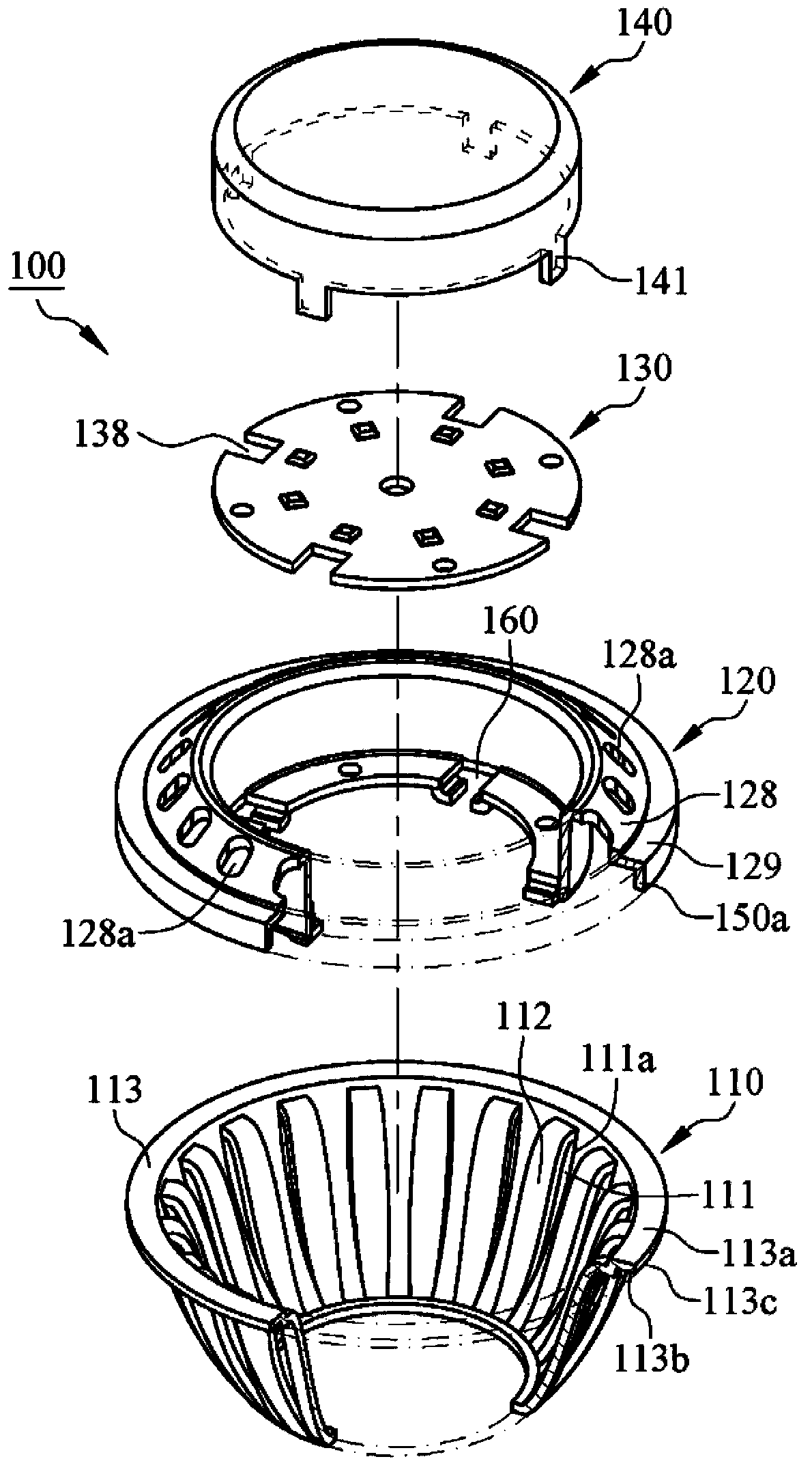
[0068] see figure 1 and figure 2 , which is the first embodiment of the present invention, a lamp installation structure 100, the lamp includes a light emitting module 130 arranged on the installation structure 100 and a lampshade 140 for emitting light from the light emitting module 130, the light emitting module 130 There are a plurality of openings 138, the lampshade 140 has a plurality of plug-in pieces 141, the mounting structure 100 at least includes a first mounting seat 110 and a second mounting seat 120 in which the first mounting seat is combined with each other, the light emitting module 130 locks Combined with the second mounting base 120, the first mounting base 110 has a plurality of heat dissipation openings 111, a plurality of heat dissipation ribs 112 and a stop portion 113, each of the heat dissipation openings 111 has a side wall 111a, and each of the heat dissipation protrusions Ribs 112 are formed on each of the side walls 111a to increase heat dissipat...

no. 6 example

[0080] see Figure 13 and Figure 14 , which is the sixth embodiment of the present invention, the difference between this embodiment and the fourth embodiment is that the first positioning plate 124 of each of the limiting members 123 has a first surface 124a, a second surface 124b and a through hole 124c, each of the through holes 124c communicates with each of the first surface 124a and each of the second surfaces 124b, each of the through holes 124c has a hole wall 124d, and each of the second positioning plates 125 of the position limiting member 123 is formed by stamping Protrudes from each of the first surfaces 124a in a manner, and each of the second positioning plates 125 is connected to each of the hole walls 124d.

[0081] see Figure 14 , Figure 15 and Figure 16 , in this embodiment, the combination of the second mounting base 120 and the base plate 131 is as follows: each of the positioning holes 134 of the base plate 131 is aligned with each of the position...

no. 8 example

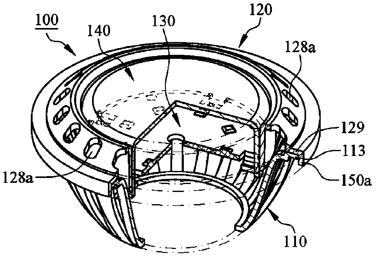
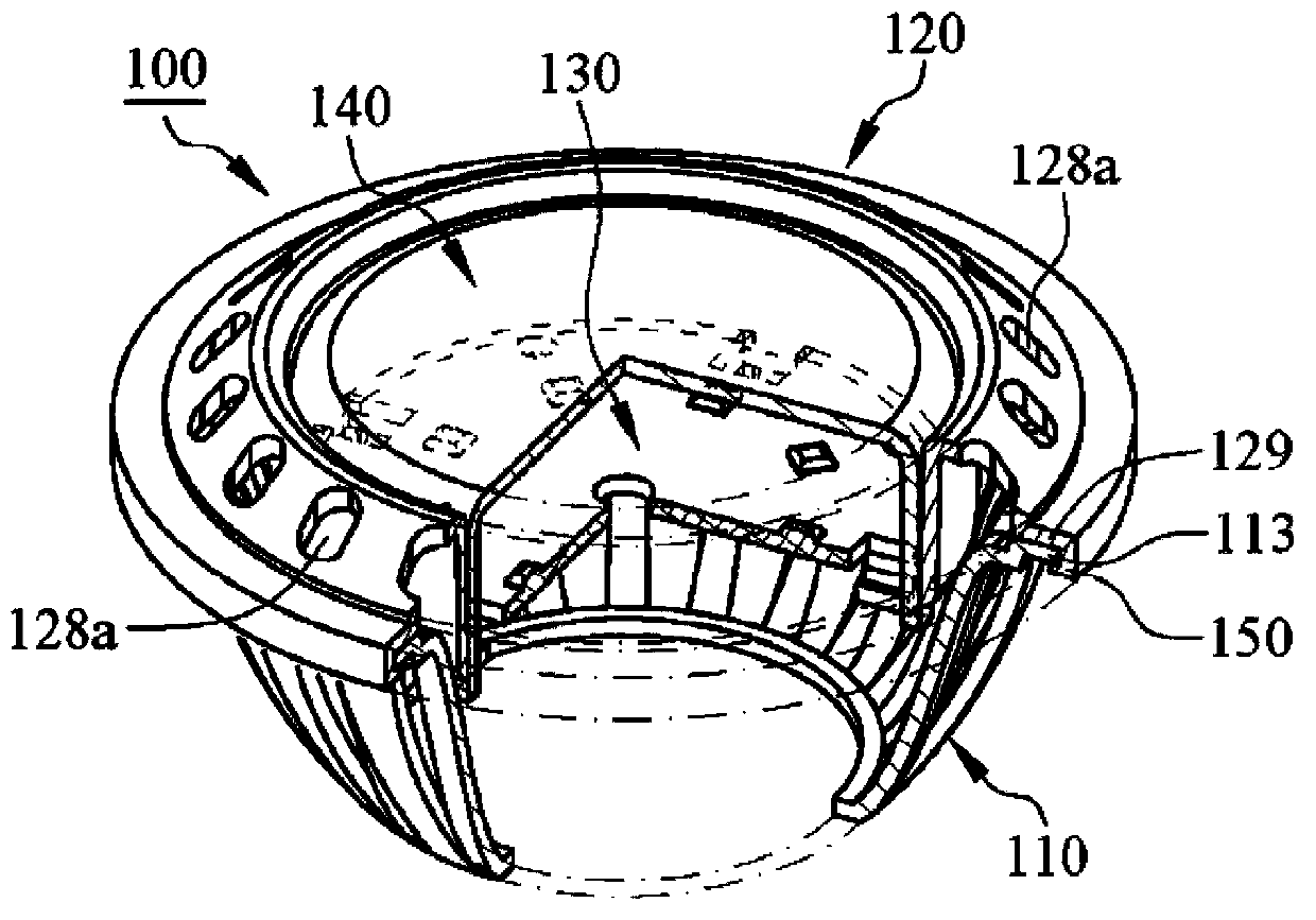
[0085] see Figure 21 and Figure 22 , is the eighth embodiment of the present invention, a lamp installation structure 100, which includes a first installation base 110 and a second installation base 120 combined with the first installation base 110, wherein the light emitting module 130 and The lampshade 140 is combined with the first mounting base 110, the first mounting base 110 has a stop portion 113, the second mounting base 120 has a limiting portion 129 and a clamping portion connected to the limiting portion 129 150 , the clamping portion 150 is deformable under force, and the stop portion 113 of the first installation seat 110 is limited between the clamping portion 150 and the limiting portion 129 to form a hidden state.


PUM


Abstract

A mounting structure of a lamp assembly at least includes a first mounting base and a second mounting base, the second mounting base is attached to the first mounting base, the first mounting base comprises a blocking portion, and the second mounting base comprises a limiting portion and a clamping portion. The blocking portion of the first mounting base is limited between the clamping portion and the limiting portion to prevent the second mounting base from separating the first mounting base. The technique scheme of the invention can simplify the assembling of the mounting structure of a lamp, and provide a beautiful appearance and high integral combination stability.

Description

technical field [0001] The invention relates to a mounting structure of a lamp, in particular to a mounting structure of a lamp having a first mounting base and a second mounting base. Background technique [0002] Please refer to China Taiwan Patent Application No. 097223212 "Light Emitting Diode Lamp", the LED lamp includes a lampshade and a colored transparent cover, the colored transparent cover has an opening, and the colored transparent cover covers a container of the lampshade The lampshade has an upper surface around the top of the accommodating groove, and the colored light-transmitting cover is arranged on the upper surface. The lampshade has a first annular structure on the upper surface. The first annular structure is used to frame the colored light-transmitting cover to prevent the colored light-transmitting cover from sliding on the upper surface. However, since the colored light-transmitting cover is only carried on the upper surface, the colored light-transm...

Claims


Application Information

Patent Timeline
Patent Type & Authority Applications(China)
IPC IPC(8): F21V17/10
CPCF21V19/0035F21V19/0045F21V29/773F21V29/83F21K9/232F21Y2115/10F21V21/00F21V17/10F21V29/74
Inventor 吴顺合黄志成
Owner TAIWAN FU HSING INDAL
Why Eureka
Try Eureka