Eureka AIR delivers breakthrough ideas for toughest innovation challenges, trusted by R&D personnel around the world.

Discharging device for heat accumulating type thermal decomposition furnace to treat pyrogenic decomposition solid products of junked tire

A regenerative pyrolysis furnace, solid product technology, applied in incinerators, lighting and heating equipment, combustion methods, etc. Problems such as stuck, avoid incomplete discharge and leakage, reduce follow-up processing costs, and reduce operating costs

Active Publication Date: 2014-03-26
北京节净环保科技有限公司
View PDF8 Cites 9 Cited by
  • Summary
  • Abstract
  • Description
  • Claims
  • Application Information

AI Technical Summary

Problems solved by technology

After the solid product obtained after tire pyrolysis is extruded by the screw, the iron wire in the solid product is separated from the carbon black, and the thin iron wire is easy to form iron balls in the discharge screw, which will cause the screw of the discharge screw device to be stuck in severe cases, affecting The normal discharge of the discharge screw, and the broken solid product is easy to form carbon black dust, part of which enters the oil and gas pipeline together with the oil and gas, adheres to the pipeline wall, and blocks the pipeline
The other part will float into the atmosphere, which will pollute the environment, and seriously affect the health of operators, pose safety hazards, and seriously affect the continuity of production

Method used


Image

  • Discharging device for heat accumulating type thermal decomposition furnace to treat pyrogenic decomposition solid products of junked tire
  • Discharging device for heat accumulating type thermal decomposition furnace to treat pyrogenic decomposition solid products of junked tire
  • Discharging device for heat accumulating type thermal decomposition furnace to treat pyrogenic decomposition solid products of junked tire

Examples


Embodiment Construction

[0022] Embodiments of the present invention are described in detail below, examples of which are shown in the drawings, wherein the same or similar reference numerals designate the same or similar elements or elements having the same or similar functions throughout. The embodiments described below by referring to the figures are exemplary only for explaining the present invention and should not be construed as limiting the present invention.

[0023] In describing the present invention, it should be understood that the terms "center", "longitudinal", "transverse", "upper", "lower", "front", "rear", "left", "right", " The orientations or positional relationships indicated by "vertical", "horizontal", "top", "bottom", "inner", "outer", etc. are based on the orientation or positional relationships shown in the drawings, and are only for the convenience of describing the present invention and simplifying Describes, but does not indicate or imply that the device or element referred...


PUM


Abstract

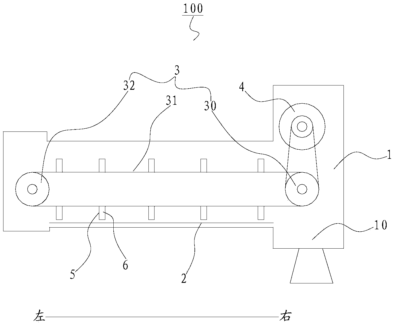
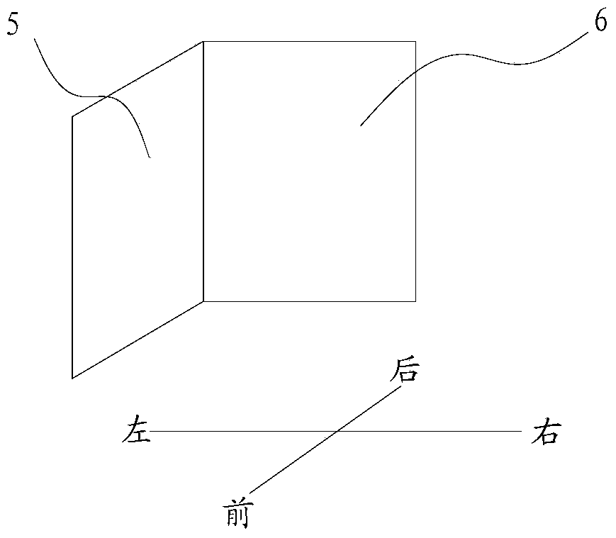
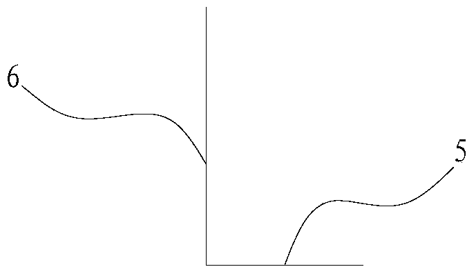
The invention discloses a discharging device for a heat accumulating type thermal decomposition furnace to treat pyrogenic decomposition solid products of a junked tire. The discharging device comprises a shell, a material laying plate used for containing the solid products, a chain board wheel transmission assembly, a driver and a plurality of material scraper blades. A discharge opening is formed in the shell. The material laying plate is movably arranged inside the shell. The chain board wheel transmission assembly is arranged inside the shell and placed above the material laying plate. The driver drives the chain board wheel transmission assembly to operate. The material scraper blades are respectively arranged on a transmission chain of the chain board wheel transmission assembly, the transmission chain drives the material scraper blades to move, and the material scraper blades push the solid products to the discharge opening. According to the discharging device, the traditional problems of material clamping, blocking and the like are solved, the continuous discharging purpose is achieved, the operating cost caused by abnormal maintenance and overhauling is greatly lowered, carbon black can be effectively prevented from being ground into powder, the potential risk caused by raised dust is avoided, and meanwhile the physical property of the solid products can not be damaged.

Description

technical field [0001] The invention relates to the field of tire treatment, in particular to a discharge device for treating waste tire pyrolysis solid products in a regenerative pyrolysis furnace. Background technique [0002] At present, in the tire continuous pyrolysis process, in order to realize continuous pyrolysis of tires, a discharge screw is usually used to directly output the solid product from the pyrolysis furnace to realize continuous discharge. After the solid product obtained after tire pyrolysis is extruded by the screw, the iron wire in the solid product is separated from the carbon black, and the thin iron wire is easy to form iron balls in the discharge screw, which will cause the screw of the discharge screw device to be stuck in severe cases, affecting The normal discharge of the discharge screw, and the broken solid product is easy to form carbon black dust, part of which enters the oil and gas pipeline together with the oil and gas, adheres to the pi...

Claims


Application Information

Patent Timeline
Patent Type & Authority Applications(China)
IPC IPC(8): F23G7/12
Inventor 吴道洪吴小飞肖磊
Owner 北京节净环保科技有限公司
Why Eureka
Eureka Blog
Learn More