Fiber gyroscope denoising method based on enhanced adaptive time-frequency peak value filtration

A fiber optic gyroscope and peak filtering technology, applied in the field of inertial navigation, can solve the problem of not finding patents and other issues

Inactive Publication Date: 2014-03-26
NANJING UNIV OF AERONAUTICS & ASTRONAUTICS
View PDF2 Cites 19 Cited by
  • Summary
  • Abstract
  • Description
  • Claims
  • Application Information

AI Technical Summary

Problems solved by technology

At present, no relevant patent...

Method used


Image

  • Fiber gyroscope denoising method based on enhanced adaptive time-frequency peak value filtration
  • Fiber gyroscope denoising method based on enhanced adaptive time-frequency peak value filtration
  • Fiber gyroscope denoising method based on enhanced adaptive time-frequency peak value filtration

Examples


Embodiment Construction

[0056] Below in conjunction with accompanying drawing, the technical scheme of invention is described in detail:

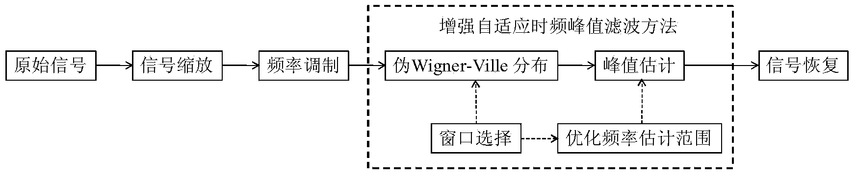
[0057] The overall flow chart of the method in this embodiment is as follows figure 1 As shown, the gyro signal is modulated into the instantaneous frequency of a frequency modulation signal, and the instantaneous frequency of the coded signal is estimated by the peak value of the pseudo Wigner-Ville distribution, and then the useful signal is restored to realize the removal of the fiber optic gyro noise. Specific steps are as follows:

[0058] 1. Signal Scaling

[0059] Let the signal model of the fiber optic gyroscope with noise be:

[0060] y(t)=x(t)+ε(t) (1)

[0061] Among them, t is the time, y(t) is the noisy output signal of the fiber optic gyroscope, x(t) is the effective signal output by the gyroscope, and ε(t) is the noise of the gyroscope.

[0062] To avoid aliasing from the encoded signal, the original signal needs to be scaled. The scaled signal ...


PUM


Abstract

The invention discloses a fiber gyroscope denoising method based on enhanced adaptive time-frequency peak value filtration. The fiber gyroscope denoising method comprises the steps of resizing a noise-containing output signal of an original fiber gyroscope, encoding the noise-containing output signal of the original fiber gyroscope into a frequency modulation analysis signal of which the amplitude value is a constant, selecting an optimal window length, optimizing a signal transient frequency estimation range, estimating a transient frequency of the frequency modulation signal according to a pseudo-Wingner-Ville distribution peak value, demodulating a transient frequency estimation peak value of the modulation signal and performing back-resizing to recover the denoised output signal of the fiber gyroscope. The method disclosed by the invention can be used for denoising signals of inertial equipment such as the fiber gyroscope. Compared with the conventional gyroscope denoising method, the method disclosed by the invention is flexible to implement, can effectively track dynamic signals such as an original signal and does not have time delay. By the adoption of the enhanced adaptive time-frequency peak value filtration method, the method can be used for optimize the frequency estimation range to obtain a better frequency estimation value of an encoded signal.

Description

technical field [0001] The invention relates to a fiber optic gyroscope denoising method, in particular to a fiber optic gyroscope denoising method based on enhanced adaptive time-frequency peak filtering, and belongs to the technical field of inertial navigation. Background technique [0002] The optical fiber strapdown inertial navigation system is small in size, high in precision, strong in reliability, high in autonomy, and relatively low in cost, and has been widely used in aviation, aerospace, navigation and other fields. As one of the core components of the inertial navigation system, the output accuracy of the fiber optic gyroscope directly affects the performance of the inertial navigation system. In actual work, affected by the noise of the surrounding environment, the useful signal of the fiber optic gyroscope is often submerged in a large amount of noise, which greatly reduces the measurement accuracy of the gyroscope. Therefore, how to reduce the influence of n...

Claims


Application Information

Patent Timeline
IPC IPC(8): G01C19/64
CPCG01C19/64
Inventor 顾姗姗曾庆化刘建业居后鸿黄磊陈维娜王云舒万骏炜赵继
Owner NANJING UNIV OF AERONAUTICS & ASTRONAUTICS
Why Eureka
Try Eureka