Anticorrosion sensor with sealed structure

A sealing structure and sensor technology, applied in the field of sensors, can solve the problems of lack of sealing effect, poor sealing effect of anti-corrosion sensors, etc., and achieve the effect of good sealing effect

Active Publication Date: 2014-03-26
CHONGQING CHUANYI AUTOMATION
8 Cites 6 Cited by

AI-Extracted Technical Summary

Problems solved by technology

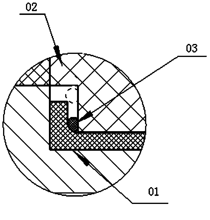
[0006] However, since the surface of the measurement component 01 is relatively smooth, when the measurement component 01 and the lower sleeve 02 of the anti-corrosion vibrator are assembled to extrude the O-ring seal 03, the O-ring seal 03 is easily extruded out of the sealing mating surface along the measurement compone...

Abstract

The invention discloses an anticorrosion sensor with a sealed structure. The anticorrosion sensor with the sealed structure comprises a measuring assembly with a shaft shoulder structure, and an anticorrosion vibrator lower sleeve, wherein the anticorrosion vibrator lower sleeve is connected to the position, arranged below the shaft shoulder structure, of the measuring assembly in a sleeved mode, the surface, corresponding to a shaft shoulder, of the anticorrosion vibrator lower sleeve serves as a sealing surface, a first sealing ring is arranged between the sealing surface of the anticorrosion vibrator lower sleeve and a sealing surface of the shaft shoulder, and an annular groove is formed in the sealing surface of the anticorrosion vibrator lower sleeve, and is used for containing the first sealing ring. According to the arrangement, the anticorrosion sensor with the sealed structure has the good sealing effect.

Application Domain

Technology Topic

Image

  • Anticorrosion sensor with sealed structure
  • Anticorrosion sensor with sealed structure
  • Anticorrosion sensor with sealed structure

Examples

  • Experimental program(1)

Example Embodiment

[0025] This embodiment provides an anticorrosive sensor with a sealing structure, which has a better sealing effect.
[0026] The technical solutions in the embodiments of the present invention will be clearly and completely described below in conjunction with the accompanying drawings in the embodiments of the present invention. Obviously, the described embodiments are only a part of the embodiments of the present invention, rather than all the embodiments. Based on the embodiments of the present invention, all other embodiments obtained by those of ordinary skill in the art without creative work shall fall within the protection scope of the present invention.
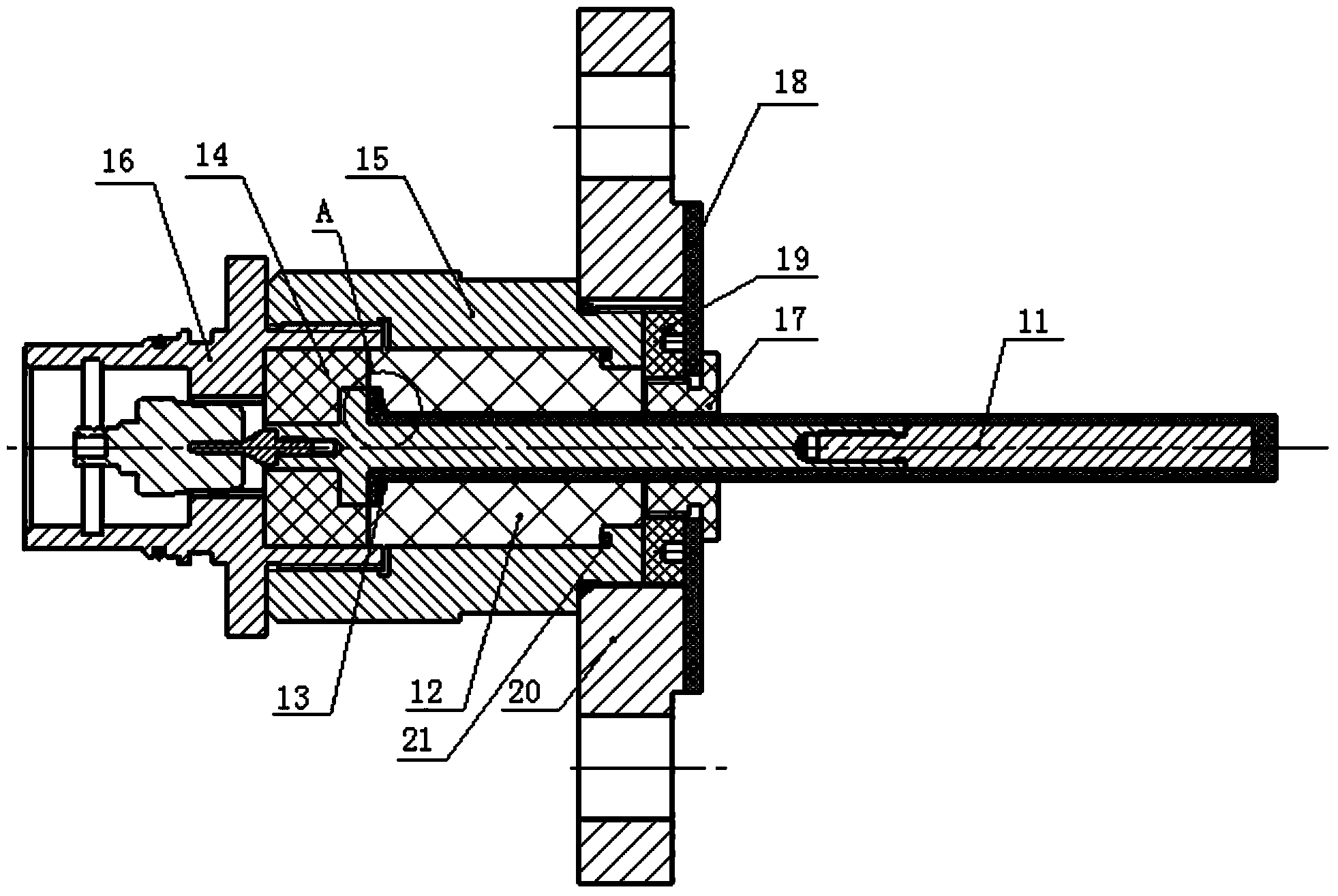
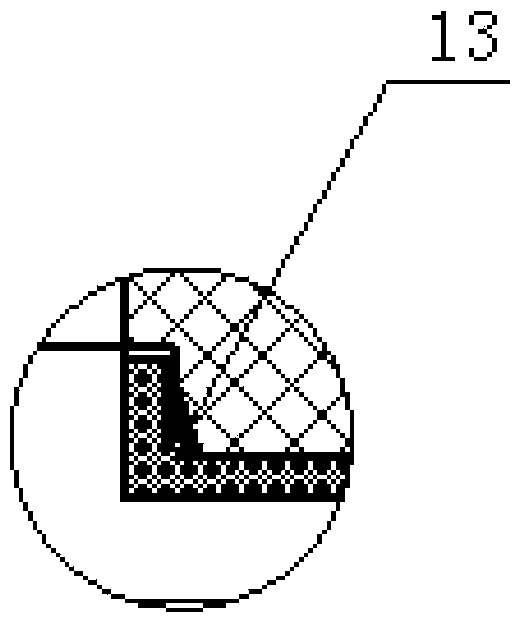
[0027] Please refer to figure 2 with image 3 , This embodiment provides an anti-corrosion sensor with a sealed structure, including a measuring assembly 11 with a shoulder structure and an anti-corrosion vibrator lower sleeve 12 sleeved below the shoulder structure of the measuring assembly 11. 12 The surface corresponding to the shoulder structure of the measuring assembly 11 is a sealing surface, and a first sealing ring 13 is arranged between the sealing surface of the lower sleeve of the anti-corrosion vibrator 12 and the sealing surface of the shoulder structure. An annular groove (not shown in the figure) for accommodating the first sealing ring 13 is provided on the surface.
[0028] Due to the anti-corrosion sensor provided by this embodiment, the sealing surface of the anti-corrosion vibrator lower sleeve 12 is provided with an annular groove for accommodating the first sealing ring 13, and the measuring assembly 11 and the anti-corrosion vibrator lower sleeve 12 are assembled and extruded. When a sealing ring is used, the first sealing ring is restricted by the annular groove and will not be squeezed out of the sealing mating surface. Therefore, the anti-corrosion sensor provided by this embodiment has a better sealing effect.
[0029] In a preferred solution of this specific embodiment, it further includes an anticorrosive vibrator upper sleeve 14 sleeved on the upper part of the shoulder structure of the measuring assembly 11, and the lower end surface of the anticorrosive vibrator upper sleeve 14 and the upper end surface of the anticorrosive vibrator lower sleeve 12 abut against each other.
[0030] With this arrangement, the anti-corrosion vibrator lower sleeve 12 and the anti-corrosion vibrator upper sleeve 14 are connected to each other, and the two are assembled into an integral protective sleeve, which can reliably seal the parts above and below the shoulder of the measuring assembly 11, which can effectively Prevent the measurement component 11 from being corroded.
[0031] In addition, because the anti-corrosion vibrator lower sleeve 12 and the anti-corrosion vibrator upper sleeve 14 are of a split structure, and the position where they are connected is located at the shoulder structure position of the measuring assembly 11, the shoulder structure of the measuring assembly 11 will not disassemble the two As a result, when disassembling the anticorrosive vibrator lower sleeve 12 and the anticorrosive vibrator upper sleeve 14, it has better maneuverability.
[0032] In order to prevent the corrosive liquid from infiltrating into the measuring assembly 11 from the butting position of the anticorrosive vibrator upper sleeve 14 and the anticorrosive vibrator lower sleeve 12, a sealing gasket is provided between the lower end surface of the anticorrosive vibrator upper sleeve 14 and the upper end surface of the anticorrosive vibrator lower sleeve 12 .
[0033] The sealing gasket is squeezed between the lower end surface of the anti-corrosion vibrator upper sleeve 14 and the upper end surface of the anti-corrosion vibrator lower sleeve 12, which in turn can play a better sealing effect, thereby avoiding the corrosion of the corrosive liquid from the anti-corrosion vibrator upper sleeve 14 and the corrosion protection. The docking position of the lower vibrator sleeve 12 penetrates into the measuring assembly 11, causing corrosion to the measuring assembly 11.
[0034] In order to further improve the sealing performance of the anti-corrosion sensor, the anti-corrosion sensor provided in this embodiment may further include a lower connecting sleeve 15 sleeved on the anti-corrosion vibrator upper sleeve 14 and the anti-corrosion vibrator lower sleeve 12, and a head sleeved on the anti-corrosion sensor There is a gap between the upper connecting sleeve 16, the lower connecting sleeve 15 and the anticorrosive vibrator upper sleeve 14 for the upper connecting sleeve 16 to be embedded.
[0035] With this arrangement, the upper connecting sleeve 16 and the lower connecting sleeve 15 can form a sealed jacket, which further seals the head of the anti-corrosion sensor and the measurement assembly 11. Moreover, since the lower connecting sleeve 15 and the anticorrosive vibrator upper sleeve 14 are provided with a gap for the upper connecting sleeve 16 to be embedded, the upper connecting sleeve 16 is embedded in the gap, which further improves the lower connecting sleeve 15, the upper connecting sleeve 16 and the anticorrosion The vibrator is covered with 14, the airtightness between the three.
[0036] In addition, a second sealing ring may be provided between the lower sleeve 12 of the anticorrosive vibrator and the lower connecting sleeve 15. In this way, the sealing performance between the lower sleeve 12 and the lower connecting sleeve 15 of the anticorrosive vibrator is improved. Further, the anticorrosive vibrator lower sleeve 12 and the lower connecting sleeve 15 are provided with a matching shoulder structure, and the second sealing ring 21 is arranged between the shoulder structure of the anticorrosive vibrator lower sleeve 12 and the shoulder structure of the lower connecting sleeve 15 . With this arrangement, the second sealing ring 21 is squeezed between the shoulder of the lower sleeve 12 of the anticorrosive vibrator and the shoulder of the lower connecting sleeve 15, and passes through the shoulder of the lower sleeve 12 of the anticorrosive vibrator and the shoulder of the lower connecting sleeve 15. The cooperation between the two has a better sealing effect.
[0037] It should be noted that in this specific embodiment, both the first sealing ring 13 and the second sealing ring 21 can be O-shaped sealing rings, of course, they can also be other types of sealing rings, as long as they have a better sealing effect. can.
[0038] In addition, it should be noted that the anti-corrosion sensor is installed on site through flanges. In the prior art, users need to select flanges of corresponding specifications according to the site conditions. The flange specifications are different and need to be designed to match. Connecting sleeve 15 under the sensor. Due to the wide variety of flange specifications, every time a flange of a specification is encountered, the structural size of the lower connecting sleeve of the sensor will be re-modified. Since the lower connecting sleeve 15 of the sensor is made of stainless steel, mass production can be guaranteed The quality of its processing, but the constant change of the size can easily cause confusion among workers on the drawings, easy processing errors, increased production costs, and it is not conducive to improving processing efficiency.
[0039] In view of this, in the preferred solution of this embodiment, the outer circumference of the measuring assembly 11 may also be provided with a locking sleeve 17 which is close to the lower end surface of the anticorrosive vibrator lower sleeve 12. The lower connecting sleeve 15 is provided with external threads, and the flange 20 is installed on the lower connecting sleeve 15 through threads. At the same time, the outer circumference of the locking sleeve 17 is provided with an annular groove, and a flange gasket 18 is inserted into the annular groove. The flange is squeezed and fixed between the flange gasket 18 and the lower connecting sleeve 15. In addition, the flange gasket 18 is detachably provided with an adjusting pad 19 on the side close to the lower connecting sleeve 15.
[0040] In this way, the flange 20 is installed on the lower connecting sleeve 15 through threads. According to different flange specifications, the flange gasket 18 can be equipped, and the flange thickness varies, and the adjustment gasket can be determined according to the flange selected by the user The size of the flange gasket 18 can be locked by the locking sleeve 17. Therefore, in the preferred solution provided by this embodiment, in order to adapt to the specifications of the flange, the lower connecting sleeve 15 does not need to be remade, and only the adjustment flange gasket 18 and the adjustment pad 19 need to be replaced.
[0041] The foregoing description of the disclosed embodiments enables those skilled in the art to implement or use the present invention. Various modifications to these embodiments will be obvious to those skilled in the art, and the general principles defined in this document can be implemented in other embodiments without departing from the spirit or scope of the present invention. Therefore, the present invention will not be limited to the embodiments shown in this text, but should conform to the widest scope consistent with the principles and novel features disclosed in this text.

PUM

no PUM

Description & Claims & Application Information

We can also present the details of the Description, Claims and Application information to help users get a comprehensive understanding of the technical details of the patent, such as background art, summary of invention, brief description of drawings, description of embodiments, and other original content. On the other hand, users can also determine the specific scope of protection of the technology through the list of claims; as well as understand the changes in the life cycle of the technology with the presentation of the patent timeline. Login to view more.

Similar technology patents

Classification and recommendation of technical efficacy words

Why Eureka
Try Eureka