
Infrared display control device and infrared display control method

A technology of infrared thermal imaging and display control, which is applied in measuring devices, radiation pyrometry, television, etc., can solve the problem that it is difficult to grasp the position and size, cannot provide users with intuitive visual help for the thermal image of the subject, and does not reflect Subject morphological characteristics, etc.

Inactive Publication Date: 2014-03-26
MISSION INFRARED ELECTRO OPTICS TECH
View PDF5 Cites 0 Cited by
  • Summary
  • Abstract
  • Description
  • Claims
  • Application Information

AI Technical Summary

Problems solved by technology

[0004] 1) During on-site operation, the user needs to manually set the type of analysis area (type of point, line, surface), position and size of the analysis area in the infrared thermal image according to the thermal image of the subject in the infrared thermal image , it is not easy for the user to grasp the set position and size, and the operation is cumbersome
[0005] 2) When the shape of the subject's thermal image or different detection purposes, it is necessary to reset or adjust the analysis area, and frequent operations are more difficult
[0006] 3) The analysis area of ​​the existing technology settings, such as Image 6 The analysis area F1 in , because it does not reflect the morphological characteristics of the subject, cannot provide users with intuitive visual assistance for the thermal image of the subject
[0007] Due to the above reasons, it becomes difficult to set the analysis area for detailed observation and analysis during infrared photography

Method used


Image

  • Infrared display control device and infrared display control method
  • Infrared display control device and infrared display control method
  • Infrared display control device and infrared display control method

Examples


Embodiment 1

[0050] Embodiment 1 uses the thermal imaging device 13 as an example of an infrared display and control device.

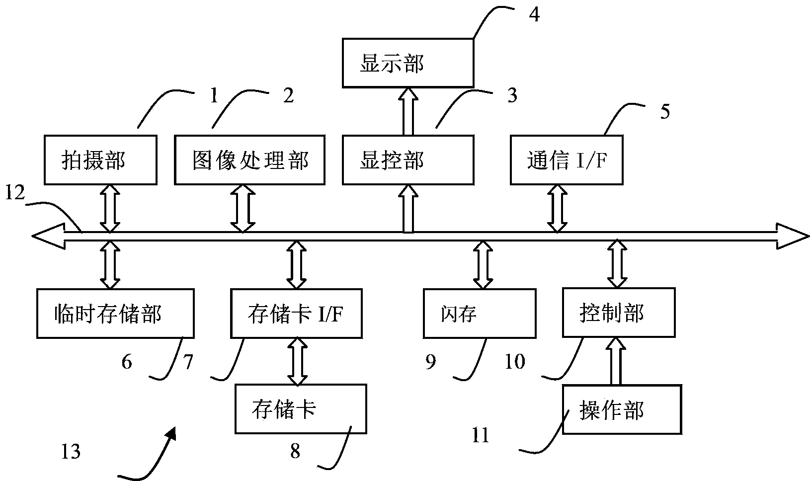
[0051] refer to figure 1 The structure of the thermal imaging device 13 of the first embodiment will be described. figure 1 It is a block diagram of the electrical structure of the thermal imaging device 13 of the embodiment.

[0052] The thermal imaging device 13 has a photographing part 1, an image processing part 2, a display and control part 3, a display part 4, a communication I / F5, a temporary storage part 6, a memory card I / F7, a memory card 8, a flash memory 9, a control part 10, The operation part 11 and the control part 10 are in charge of the overall control of the thermal imaging device 13 by connecting with the above corresponding parts through the control and data bus 12 . The control unit 10 is realized by, for example, a CPU, MPU, SOC, programmable FPGA, or the like.

[0053]The imaging unit 1 is composed of unillustrated optical components, le...

Embodiment approach

[0054] The image processing unit 2 is used to perform specified processing on the thermal image data obtained by the shooting unit 1. The processing of the image processing unit 2, such as correction, interpolation, false color, synthesis, compression, decompression, etc., is converted into a suitable display, Handling of data such as recording. The image processing unit 2 is used to perform prescribed processing on the thermal image data captured by the imaging unit 1 to obtain image data of infrared thermal images. For example, the image processing unit 2 performs non-uniformity correction on the thermal image data acquired by the imaging unit 1 , interpolation and other prescribed processing, perform pseudo-color processing on the thermal image data after the prescribed processing, and obtain image data of infrared thermal images; an implementation of pseudo-color processing, for example, according to the range or AD value of thermal image data (AD value) The setting range ...

Embodiment 2

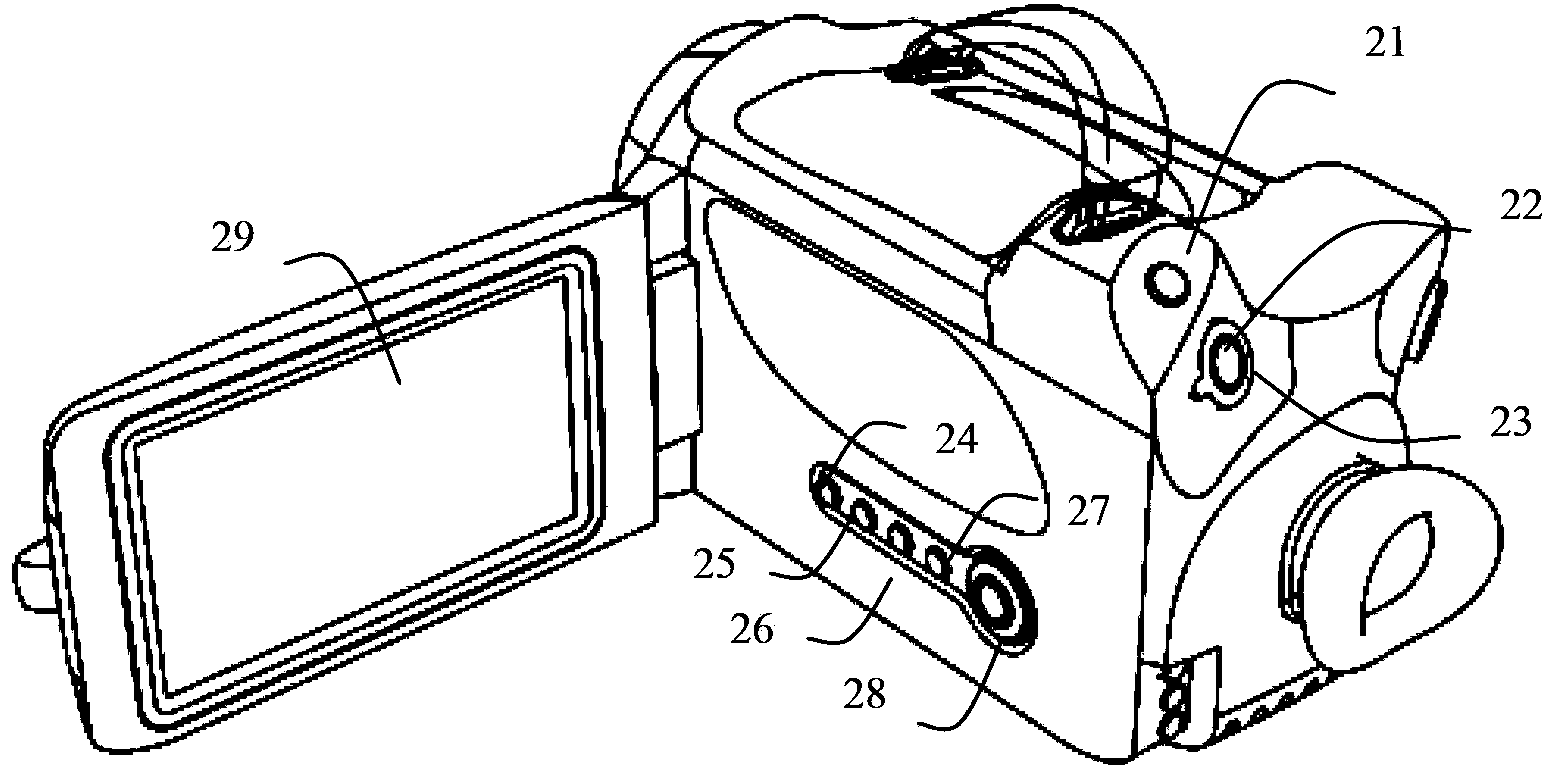
[0197] The control flow of Embodiment 2 will be described in detail below. Embodiment 2 is to have with figure 1 In the thermal imaging device 13 shown with the same structure, the analysis and display control program different from that of Embodiment 1 is stored in the flash memory 9; Figure 4storage contents shown. Different from the operation in Embodiment 1, the user's operation is: press the mode key 25 of the operation part 11 to enter the reference mode, and when the analysis area needs to be displayed, press the analysis key 26 to display the analysis area.

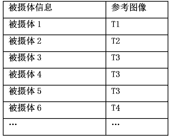
[0198] refer to Figure 21 To illustrate the configuration set by the user through "Reference Image CD3". Reference image: "datum 1"; position rule: datum 1, adaptive, adaptive zone Z1, centered; compositing parameters: transparency rate 1, datum 1 is "blue".

[0199] The user configures "Switch One" in the frozen state through the configuration of "Switch CD4". Among them, "switch one" such as Figure 22 ...


PUM


Abstract

The invention discloses an infrared display control device and an infrared display control method, and relates to the application fields of thermal image devices and infrared detection. According to a thermal image device in the prior art, an analysis region needs to be set relying on the subjective experience of a user in the shooting process, so the operation is complex. At a specified position of an infrared thermal image, continuous synthesis is performed between a reference image which has a specified size and used for embodying the predetermined morphological characteristics of a shot object and the infrared thermal image to enable the simultaneous presentation of the shot object thermal image and the reference image, the reference image is taken as the visual reference for shooting the shot object thermal image, the reference image is used to perform visual prompt on the imaging morphology of the shot object and display an analysis region corresponding to the reference image at the same time, the reference image is taken as the reference for shooting, a standard shot object thermal image can be acquired so as to perform estimation on the shot object thermal image through the analysis region corresponding to the reference image, advantages of low user technical requirements and easy operation can be realized, so that an ordinary user can have good shooting skill level.

Description

technical field [0001] The infrared display and control device and the infrared display and control method of the present invention relate to thermal imaging devices and the application field of infrared detection. Background technique [0002] In infrared detection, when the subject needs to be carefully observed or further analyzed, it is necessary to set an analysis area for the subject's thermal image in the infrared thermal image, where the analysis area is such as a point, line, surface and other regional units or multiple A combination of regional units, Image 6 The area units S01 and S02 in the middle analysis area F1 represent the parts that need to be carefully observed in the thermal image of the subject. [0003] In the prior art, the operation of setting the analysis area is very inconvenient, mainly because: [0004] 1) During on-site operation, the user needs to manually set the type of analysis area (type of point, line, surface), position and size of the a...

Claims


Application Information

Patent Timeline
IPC IPC(8): G01J5/02H04N5/232H04N1/21
Inventor 王浩
Owner MISSION INFRARED ELECTRO OPTICS TECH
Learn More