An Integrated Test Method for Vehicle Energy Flow Analysis

A technology of integrated testing and energy flow, applied in vehicle testing, machine/structural component testing, measuring devices, etc., can solve the problem of not being able to obtain the energy consumption distribution map, etc., to shorten the development cycle, reduce the number of tests, and save costs Effect

Active Publication Date: 2015-12-02
CHONGQING CHANGAN AUTOMOBILE CO LTD
View PDF5 Cites 2 Cited by
  • Summary
  • Abstract
  • Description
  • Claims
  • Application Information

AI Technical Summary

Problems solved by technology

The existing method for testing the real-time state parameters of the vehicle is to test the parameters of each subsystem separately. The environment or working conditions are different in each test. If the test results are used for energy flow analysis, the real energy cannot be obtained. Consumption distribution map

Method used


Image

  • An Integrated Test Method for Vehicle Energy Flow Analysis
  • An Integrated Test Method for Vehicle Energy Flow Analysis

Examples


Embodiment Construction

[0013] The present invention will be further described below in conjunction with accompanying drawing.

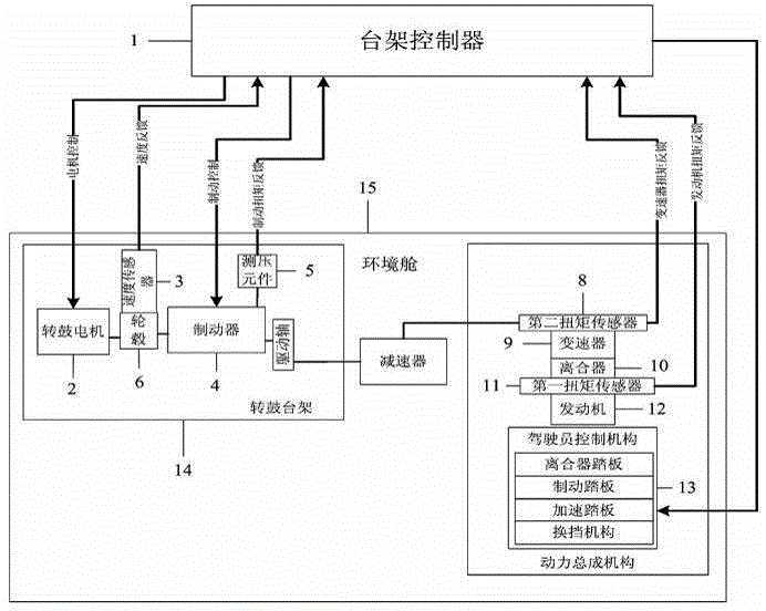
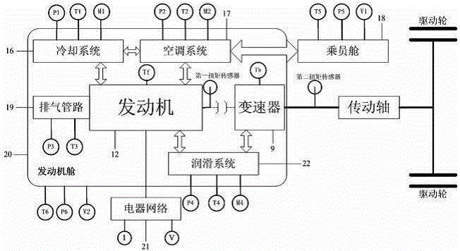
[0014] Such as figure 1 , figure 2 As shown, the integrated test method for vehicle energy flow analysis includes the following steps:

[0015] 1) Install the test components of the power transmission system; install the first torque sensor 11 between the crankshaft output end of the engine 12 and the clutch 10, install the second torque sensor 8 at the output end of the transmission 9, and install the load cell 5 on the brake 4 , the speed sensor 3 is installed on the hub 6, the output of the first torque sensor 11, the output of the second torque sensor 8, the output of the load cell 5 and the output of the speed sensor 3 are all connected to the bench controller 1;

[0016] 2) Install the test components of the cooling system, air conditioning system, exhaust pipeline, lubrication system and electrical network connected to the engine; install the coolant pressure sens...


PUM


Abstract

The invention discloses an integration testing method for analyzing the energy flow of a finished automobile. The method comprises the steps of installing a testing element of a power transmission system, installing a cooling system, an air conditioning system, a gas exhaust piping, a lubricating system, and a testing element for testing the network of an electric appliance, installing testing elements for a passenger compartment and an engine compartment, creating a testing environment, and testing and recording the real-time parameters of the above subsystems, wherein the cooling system, the air conditioning system, the gas exhaust pipe, the lubricating system and the testing element for testing the network of the electric appliance are connected with an engine. By the testing method, the real-time parameters of various subsystems of the same automobile under the same environment and working conditions are recorded, and the requirements of the analysis of energy flow of the finished automobile on the real-time parameters of the various subsystems are met.

Description

technical field [0001] The invention relates to a vehicle testing method, in particular to an integrated testing method for energy flow analysis of a complete vehicle. Background technique [0002] The energy flow analysis of the whole vehicle is to analyze the energy consumption of each subsystem and each component from the perspective of the whole vehicle, and obtain the energy consumption distribution map from fuel to wheels. The establishment of a vehicle energy flow analysis platform can use fast and low-cost control strategy optimization to achieve the purpose of reducing vehicle fuel consumption. In order to analyze the energy flow of the vehicle, it is necessary to collect real-time working state parameters of each subsystem related to energy consumption. Due to the coupling relationship between the subsystems of the vehicle, the working status of each component affects each other. In order to obtain the real real-time energy consumption of each subsystem and compon...

Claims


Application Information

Patent Timeline
Patent Type & Authority Patents(China)
IPC IPC(8): G01M17/007
Inventor 聂相虹詹樟松杨柏林胡铁刚刘斌李燕
Owner CHONGQING CHANGAN AUTOMOBILE CO LTD
Why Eureka
Try Eureka